
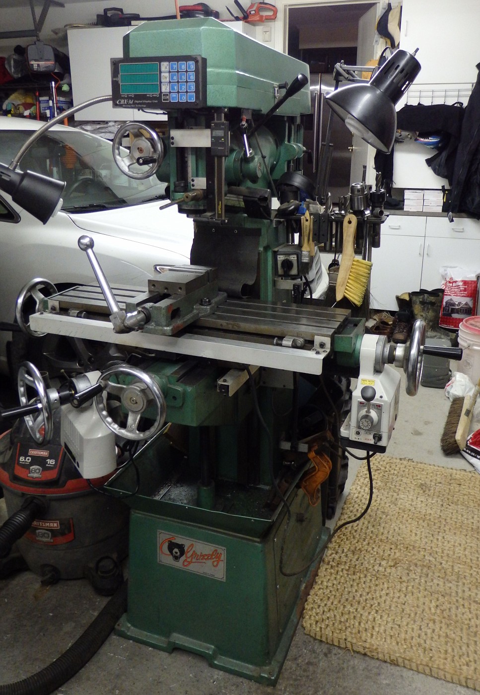
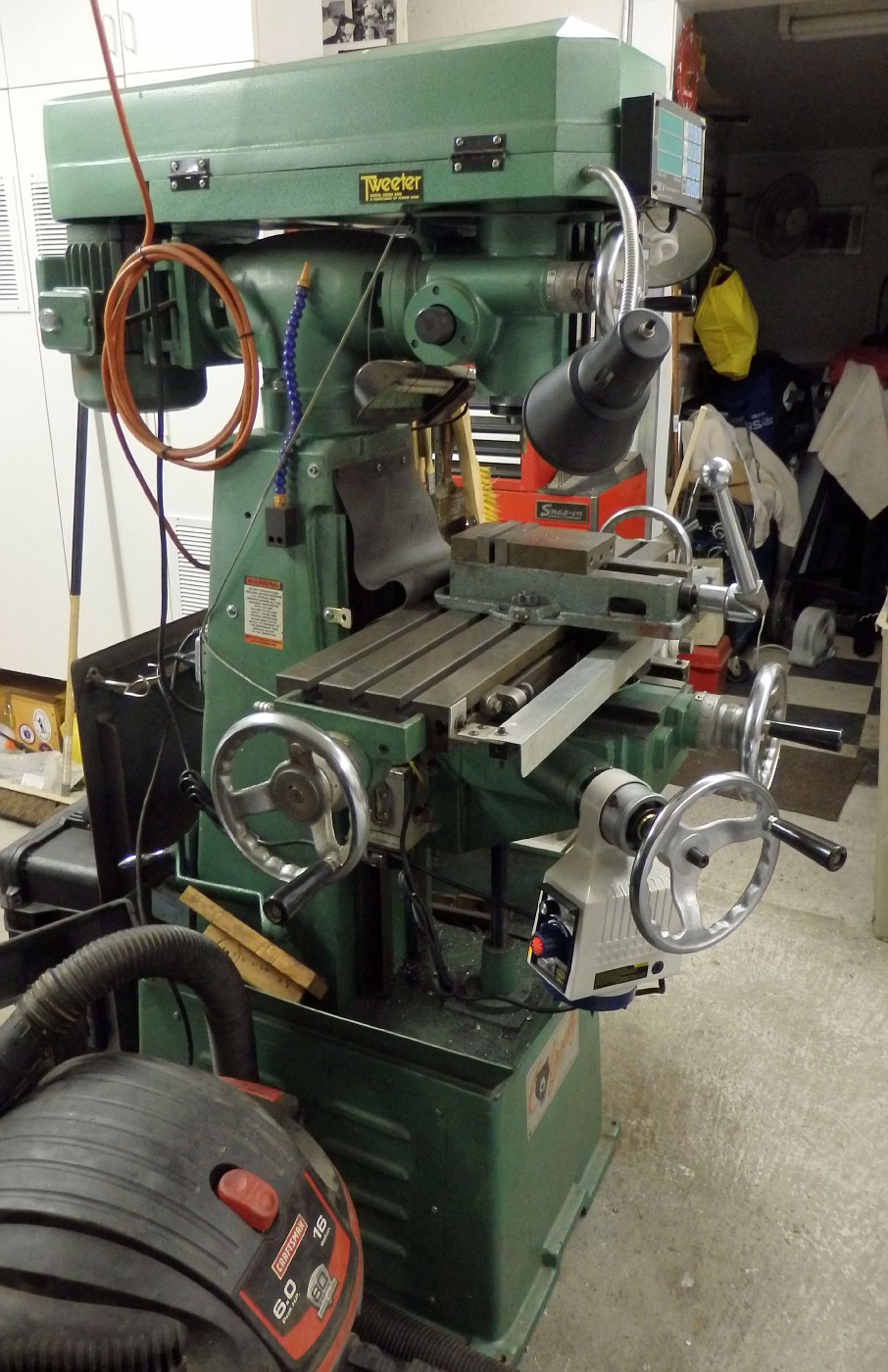
I have a Grizzly milling machine that I’ve wanted to power the Z axis knee for some time. I decided that rather than trying to fabricate something I’d just bite the bullet and buy a power drive kit for the Z axis. My research, and pocketbook, led me to Shars  Tool Company and the Model APZ150 Power feed kit. At the time of this writing, 2-20-15, this kit sold for $350.
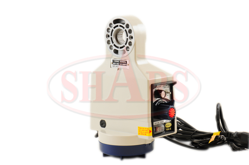
http://www.shars.com/products/view/20357/APZ150_Milling_Machine_Power_Feed_Z_Traverse_150_Lbs
This drive offers some nice features….150 inch pounds torque / Rapid Speed Button / Jog Function / Electro-Magnetic clutch to offer instant reverse direction without damage
The unit comes very well packaged with everything you need to install it on the Z knee axis of your milling machine.
For my installation, a lathe was required and I’ll explain why in the body of this article
The first order of business was installing the mounting ring that is included with the kit. It has a small flange that would help center it on the Z axis boss. But in my milling machine’s case, it was too proud and needed to be turned down in the lathe.
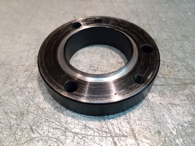
Three holes were then drilled and taped for the 6mm metric bolts provided
with that done, the mounting ring is bolted in place. Be sure the two threaded mounting holes for the drive unit are in the correct location and level before you drill and tap your holes.
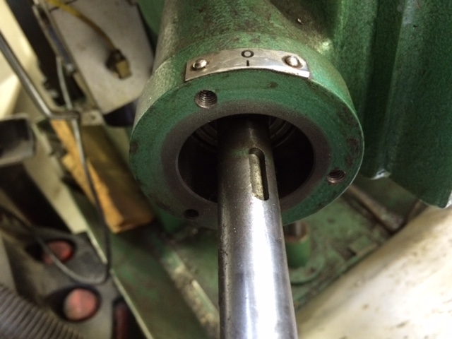
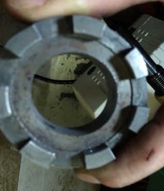
Next was the main shaft also provided in the kit. This was a bit of an issue. The hole bored in this piece is supposed to be 5/8″ and able to slip right over the existing shaft. The hole bored in the piece I received was just slightly undersized and needed to be bored out a bit. Unfortunately the longest boring bar I had was only 5″ and I need to bore it about 6″. So I had to remove 1″ from the Z axis shaft on my lathe.
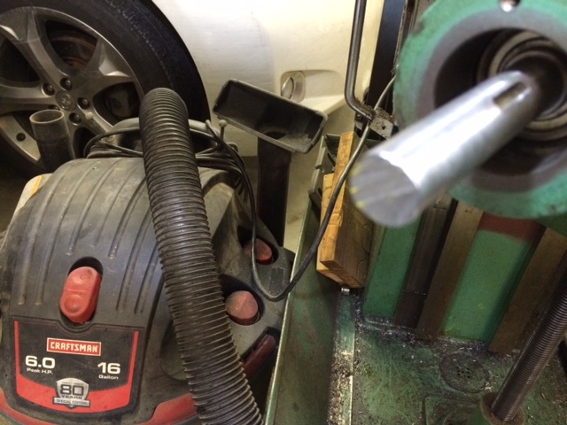
I hate cutting on a machine like this but my only other choice was wait until the next day and buy a longer boring bar or a 5/8″ drill bit that I’d probably never use again. I kept the piece I cut off. I can always weld it back on if necessary.
Sorry I didn’t take a picture of this adapter shaft by its self.
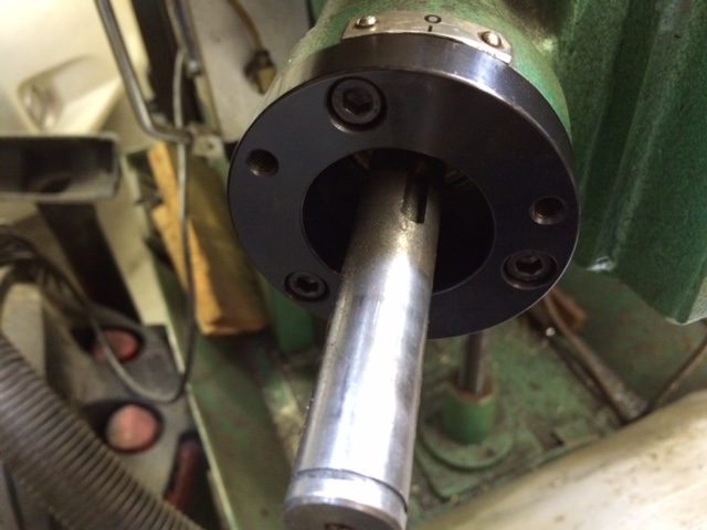
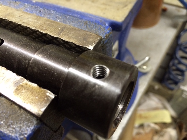
The adapter shaft was drilled and taped for a 1/4-20 set screw
And installed on the milling machine

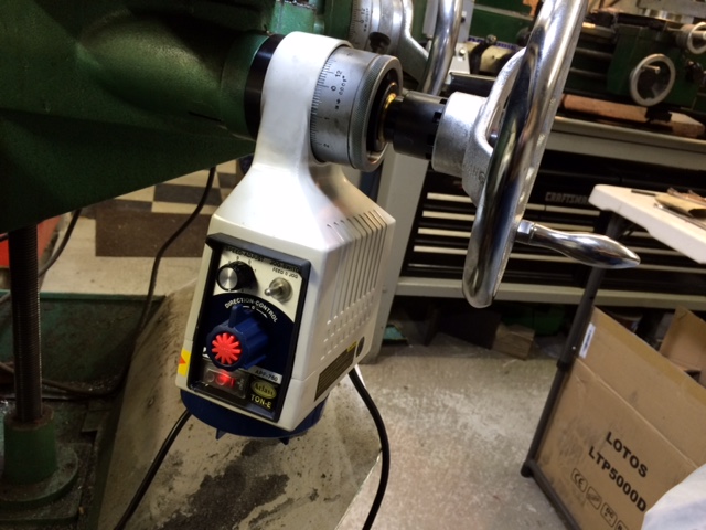
Next step is installing the drive unit
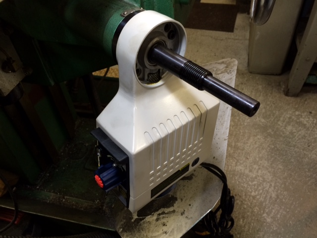
The drive unit is attached to the adapter ring with two 6mm bolts into the supplied drilled and tapped holes
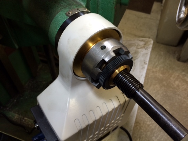
The main bronze drive gear and the ring that holds your original scale are installed next. The drive gear is indicated with a key way and key that are supplied with the kit.
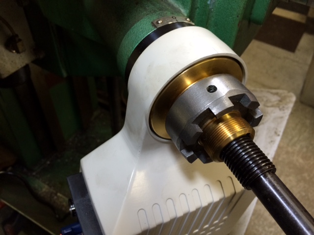
The hole in my milling machine’s scale ring was too small. Once again the lathe was called into action to open up the hole in my piece
That done, installed and set screw locked down and the retaining nut is threaded on
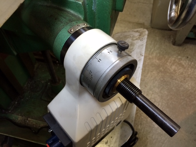
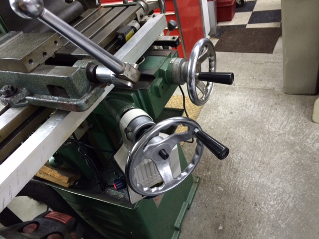
and the scale is slid into place
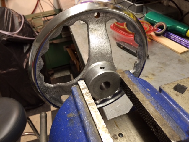
I replaced the long “L” shaped crank that came with the milling machine with an 8″ hand wheel that was sourced from Grizzly. This is for safety as I didn’t want that long crank spinning around banging me in the shins! This hand crank is supplied with a 1/4″ hole bored. It was put in the lathe and bored out to 5/8″ and a set screw hole was drilled and taped.
The locking nut was installed along with the hand wheel. The locking nut supplied has drive teeth that might be useful in another type of installation. In my case it was simply used as a nut.
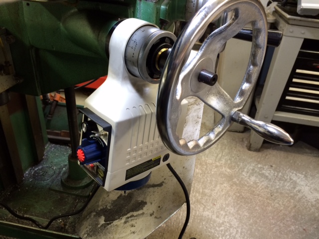
Lastly, I changed the handwheel knob with the one from the crank….More Better!
So there you have it…………Only took two hours and it works like a charm! Check out the video here:
http://public.fotki.com/Rbertalotto/machine_tool/milling-machine-sha/img-0168.html
If that link doesn’t work you can view it on YouTube:
Hope you enjoyed this article………….Be Safe!
 UPDATE!!!
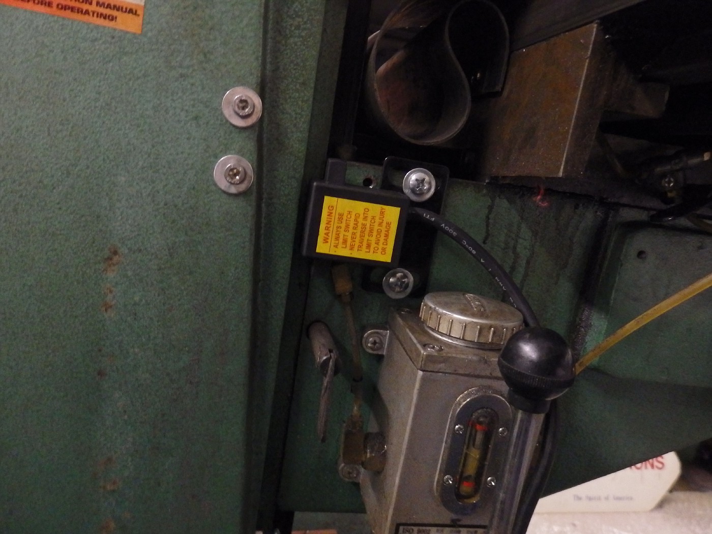
I installed the auto stops this morning.
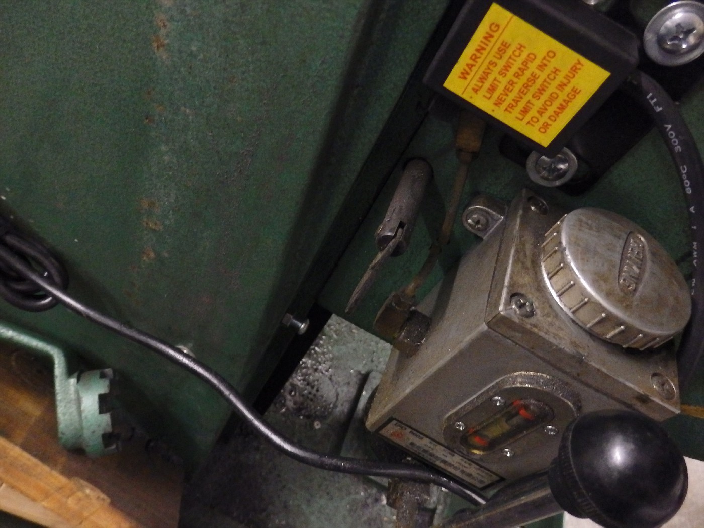
The switch box was simply mounted to the knee with two drilled and taped holes
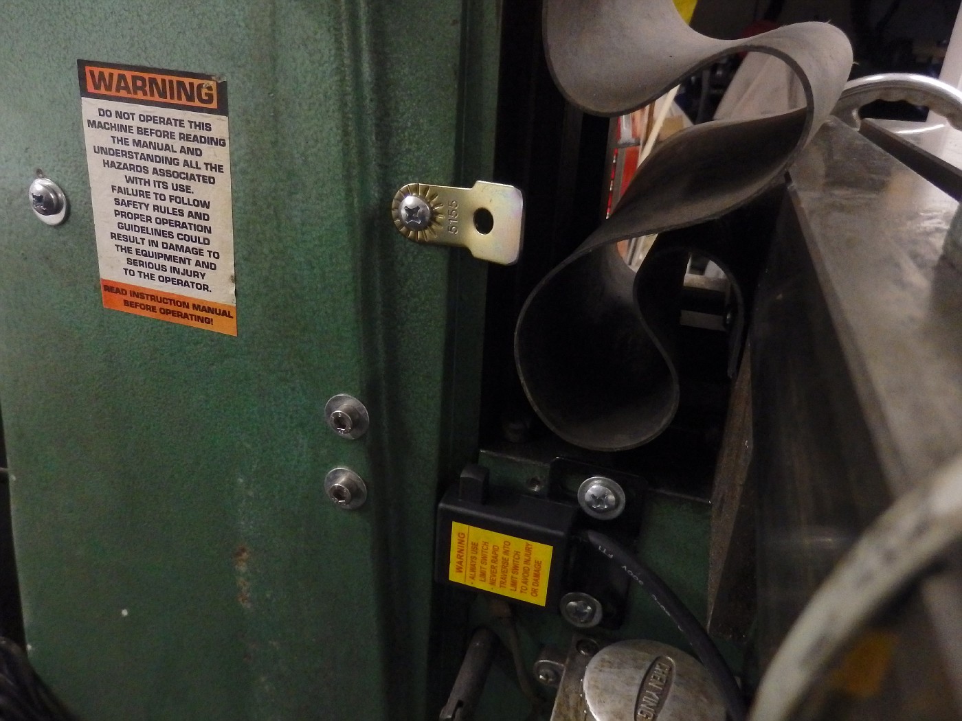
For the “UP” stop I made a like part from a piece of metal I found in the scrap box. I will not be using the stops in production so I made them non adjustable. They stop before the vise hits the chuck.
The “DOWN” stop is a simple bolt in a threaded hole. A little hard to see.
The kit comes with two pieces of “H” shaped extruded aluminum rails and adjustable stop “buttons” that could be mounted if you wanted to have the knee stop a various points. Â I didn’t think I’d be using this drive in that way so I didn’t use them. Theses “Stops” are simple there to hopefully “Stop” me from doing something stupid!
When I mounted the switch, I realized the UP and DOWN switches were reversed. You can easily take the switch apart and swap the two switches. Takes all of ten minutes.
Thanks