
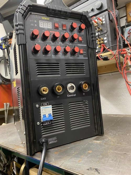
Don’t get me wrong. I love my PrimeWeld 225X AC/DC TIG-Stick welder. Simply a fantastic machine…..even if it cost twice as much. Selling for under $1000 with top quality build, accessories and warrantee…It’s the bargain of the century!
But why on God’s Green Earth did they put the power switch on the back of the cabinet…Where it is nearly inaccessible when the welder is mounted on a cart with tanks or close to a wall. Some suggested it was a European code thing……Whatever, it needs to move to the front where switches belong.
BUT FIRST…UNPLUG THE WELDER!!!!
Then you need to remove a few dozen screws to get the cover off….I was surprised to see that most of the screws were using threaded holes and not just cheap sheet metal screws…. NICE!
Also, once inside the construction, wiring and general layout is very impressive. How do they do this for under a Grand!
Once you have the cover off, using a Philips head screw driver and a needle nose pliers to hold the tiny nuts, remove the power switch…….(I hope I didn’t have to remind you to unplug the welder first……)
Once the switch is out, mark the wires with tape and magic marker as to where they belong and disconnect them.
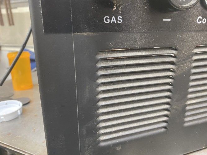
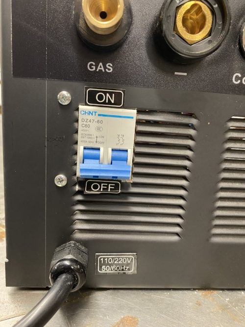
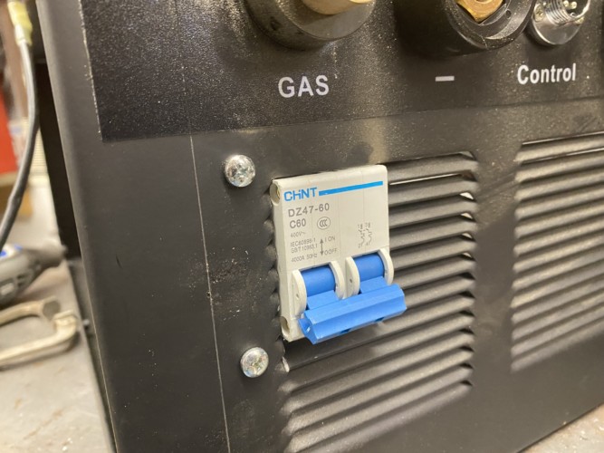
I decided the easiest place to mount the switch was on the front panel, lower left, in one of the air vents just under the GAS inlet..
This is the area inside the cabinet where there is lots of space to relocate the switch.

Using a Dremel Tool with a cutoff wheel a removed a section of the air vent
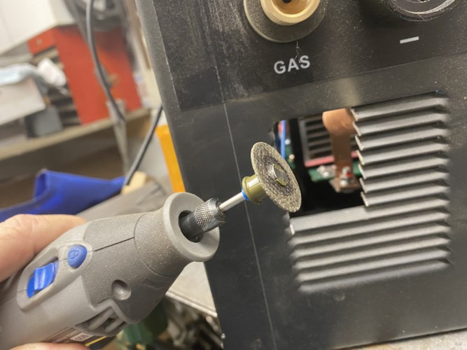
And I ended up with a nice square hole….Easy Peasy!

Next I bent a small piece of steel and drill a couple mounting holes to secure the switch in the newly cut opening.
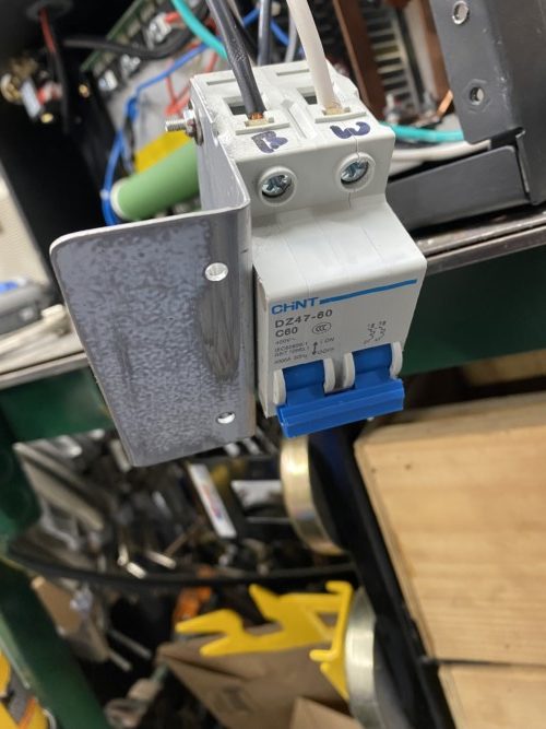
Using the factory supplied nuts and bolts to secure the bracket to the switch
I decided that one bracket was plenty. The switch is very easily “flicked” and with a good solid mount on one side it is very secure.
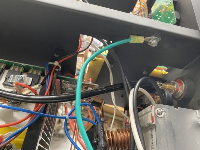
The wires from the welders circuit board needed to be extended. I used 10g THHN wire that I had in my junk box. Using heat shrink crimp connectors accomplished this task.
I wanted to replace these two wires right from the circuit board as it appeared that they terminated with simple spade connectors to the board. But try as I might, I couldn’t pull the wires off the board! I was afraid of damaging the circuit board if I pulled to hard so I decided to just extend them.

The power cable was removed from the rear and relocated through a 1/2″ hole drilled into the cabinets lower left. This is to keep the high voltage AC line within the cabinet as short as possible and as direct as possible to the switch.

The switch and bracket with wires attached was now mounted to the front panel of the welder with two small nuts and bolts…Through two holes drilled into the front panel and the bracket
( I was able to carefully remove the on/off and power stickers from the back and reuse them)
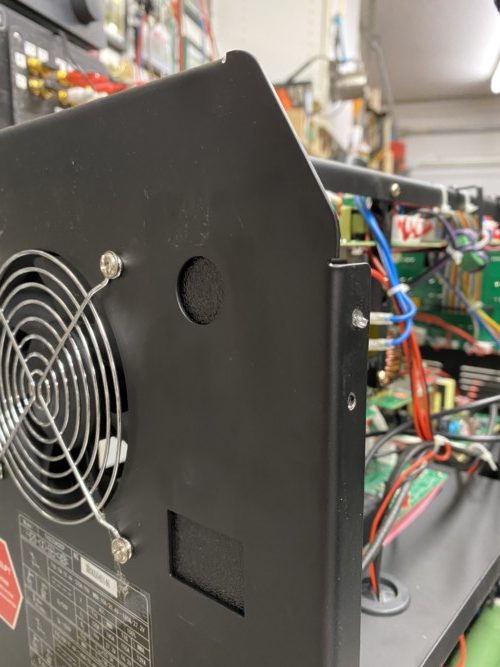
Rear view

The ground wire found a new home secured to the panel running across the cabinet. A new hole was drilled and the paint ground off to secure a good, positive ground……(Positive Ground….interesting use of words….)
I then covered the two rear holes where the switch and power wire used to enter the cabinet with a couple small pieces of ABS plastic and some 3M VHB tape. Don’t need no mice setting up home in there!
Put the cover back on and crank it up!
That about sums it up. Took about an hour and a half to accomplish. Love this modification!
Thanks for reading! Have a great day!


Be sure to visit my many other articles on Gunsmithing, RVing, Boats, Electric Tractor Conversions and other Garage Mayhem at
RVB Precision | Welcome to the world of ultra precision
And my YouTube channel…Search “Roy Bertalotto” on YouTube