
I had been reading lots of reviews on this amplifier kit offered by Dan Joffe who owns www.updatemydynaco.com and www.akitika.com . Update My Dynaco is exactly that. A source for all kinds of kits and parts to Update vintage Dynaco Solid State Amplifiers and Preamplifiers. AKITIKA is a site to purchase solid state amplifier and preamplifier kits.
I was putting off buying one of these Z4 amplifier kits until the winter, but then I read that the “chip” that this kit uses in no longer available and the new version would use discrete components which would be more soldering and more assembly…. I decided to jump on it and order one and put it away until winter as lots of other projects were taking my attention. (You should contact Dan at AKITIKA on availability of this kit or the replacement)
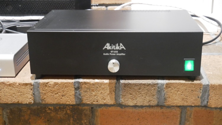
The ALITIKA Z4 is actually a version of the “GT-102” Amplifier kit. The standard GT-102 is fine with 8ohm speaker loads, but not so great if the speakers are 4 ohm rated. The Z4 has a modification to deal with these lower impedance load speakers. All the info on this is on the AKITIKA web site.
Since I will be using this amplifier with Magnepan LRS, which are 4 ohms, I ordered the Z4. And I ordered the optional volume control. I change speakers often while reviewing them and I like to turn down the gain right at the amplifier while doing this.
It arrived within a couple days, very well packed and sorted. There were multiple bags of parts based on the assembly order. A very nice, heavy cabinet, a toroidal power transformer and four circuit boards of very high quality.
First order of business is inserting components into the Power Supply board and soldering them in place and mounting this assembly to the included heat sink.

Next is inserting and soldering components into the two amplifier circuit boards and mounting them to the heat sink.

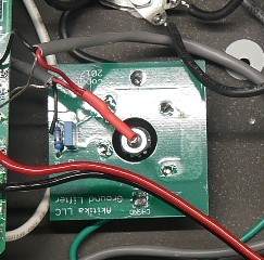
Next is building the “Ground Lifter” board and installing it into the floor of the cabinet
Next is a whole bunch of mechanical assemblies and installs, feet, speaker binding posts, RCA jacks, power switch, power cord, etc….

Now is time for that “Honking” (Heavy) Toroidal power transformer. It is bolted through the floor of the cabinet and oriented in a particular way according to the instructions.

At this point, I decided to install the volume control. But I moved it to the center of the face plate as I just thought it looked better there. Your call…..But I’m sure Dan had a reason to install it far from the power switch. Just be aware that there is a shielding partition that runs down the center of the amplifier. Be sure the volume control doesn’t interfere with this.
Once all the boards and the power supply are wired up as the instructions indicate, it time for some testing…. Here is where you need a reasonably good VOM (Volt Ohm Meter)…..(I used a digital one I bought a while ago for under $50)
First test is the “Power Supply” test…BE CAREFUL! You are poking around in an open top piece of electronics equipment, plugged into lethal voltages! I’m not going to get into this whole testing sequence, but simply say you are testing the power supply board for proper output voltage to the amplifier boards.
In my amplifier, I had an issue. The voltage tested as required, but then it slowly faded in DC volts. I had no idea what was wrong. I sent Dan an email and he called me back within a few minutes and we figured out the issue and resolved it. Back in business!
Now that we have a properly functioning power supply, the next test is the “Power Off” test….We are looking for around 1000 ohms between the Red and the Black binding posts……. PASSED!
Next test is the “POWER ON” test …. NO SMOKE! That’s good!….Green LEDs light up on the circuit boards..GOOD!….Speaker Relays “click”..GOOD!…. Measure DC voltage on the speaker binding posts, should be less than 1v…GOOD!
So now we install the top cover and hook up some speakers and see if this thing can make music.
When I turned up the volume on the preamplifier, one channel was about 25% in volume from the other channel……. “Calling Dan!”…….Once again he got right back to me and guided me through some tests with the meter and we figured out the issue. No big deal…..NOW WE GOT MUSIC! (Be aware, the issues I had are not typical by any stretch. I only bring them up to show the fantastic support that Dan offers with a purchase of a kit. Most kit builders could have figured out what was wrong without support. But it was a good test so future builders feel comfortable getting into kit building)
So how does it sound?….In a word…”FANTASTIC!”……I have a few different amplifiers to compare it to. My reference amplifier is a PASS LABS First Watt F5v2 Class A 50wch amplifier. It is magnificent! (you can read all about that adventure here: http://rvbprecision.com/stereo/nelson-pass-first-watt-f5-turbo-v2.html )
I was very surprised in how close this amplifier sounded to the Pass Labs…….
I tried it with both KEF LS50 Metas and Magnepan LRS…It is great with either speakers. For under $400 it simply can’t be beat!
So lets look at some likes and dislikes with this whole kit:
The GOOD:
Very high quality parts
Very well done assembly manual
Fantastic support from Dan if you need it. (This is huge in the Kit Build World)
Top performance sound quality
Price!
The BAD:
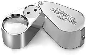
I do not suggest this kit for a first time builder with little electronics experience. Some of the electronic components are so small that to identify the writing on them or the color bands on the resistors I had to use a Jewelers Loupe!
The solder lands on the circuit boards are very close together. You can’t assemble this with a ‘Soldering GUN”. You need a very fine tip soldering iron and high quality solder……..And you really need to know how to solder. I’d suggest you buy a couple $35 amplifier kits from Jerry’s Electronics to practice on. These are simple Class D amplifiers that you power with an old laptop power supply. You will be amazed at the sound quality. But more importantly, if you screw it up you are only out $35!
https://www.jerryselectronics.com/diykits/diykits.htm

If all of this makes you uncomfortable, you can simply buy this amplifier totally assembled from Dan….
And THE UGLY:…..There isn’t any! This is a fantastic piece of HiFi equipment. In my estimation worth three or four times what we are paying for it. And it’s a total blast building something and then using it to impress your Brother-In-Law!
Here is some more info:
- Output Power: greater than 50 Watts per channel into 4 Ohms
- Small Signal Bandwidth: typically wider than 5 Hz to 100 kHz at -3 dB points
- Slew Rate (typical) 14 Volts/microsecond
- Damping Factor @ 1 kHz wrt 4 Ohms: >40
- Signal to Noise Ratio: typically 133 dB below 50 Watts into 4 Ohms, A-weighted, referred to a shorted input.
- Harmonic Distortion: typically 0.006% at 50 Watts into 4 Ohms at 1 kHz. Clipping (typical) occurs at a bit more than 68 Watts into 4 Ohms at 1 kHz.
- Intermodulation Distortion: 0.004% typical, SMPTE 4:1, 60 Hz, 7 kHz
- Separation: >90 dB at 1 kHz, >70 dB at 10 kHz
- Input Impedance: 51 K Ohms
- Sensitivity: 0.777 Volt RMS input produces 16 Volts RMS output
- Dimensions: 15″ Wide x 10″ Deep x 4.5″ Height (includes height of the feet)
- Input Power: 120 VAC 60 Hz, IEC connector (power cord supplied)
- Input Power Fuse Rating and type: medium acting 3 Amps or 3.15 Amps, 5×20 mm
- 220-240 Volt operation also possible with the V240 kit, which uses a 1.5 Amp fuse
- Weight: 15.5 lbs
- Shipping Weight: 19 lbs
From the AKITIKA web page:
We rate the Z4 version of the GT-102 at 50 watts per channel into 4 Ohms. It will typically deliver 64 WPC at low distortion, and around 68 WPC at 1% THD. We’ve made additional measurements of the output power as a function of load impedance. These measurements were made on a unit picked randomly from stock, with a single channel driven at 100 Hz. They are summarized here. We include the temperature of the heatsinks that rise with time as we let the amp deliver continuous power.:
- 64 Watts delivered in 4 Ohms at 0.0063% distortion and a heatsink temperature of 29 C
- 64 Watts delivered in 4 Ohms at 0.0063% distortion and a heatsink temperature of 53 C
- 64 Watts delivered in 4 Ohms at 0.0063% distortion and a heatsink temperature of 62 C (steady state)
We next did a series of tests delivering continuous power at 1 kHz into other impedances
- 35 Watts into 8 Ohms at 0.002% THD
- 38 Watts into 8 ohms with 1% THD
- 64 Watts into 4 Ohms with 0.0061% THD
- 68 Watts into 4 Ohms with 1% THD
- 82 Watts into 2.67 Ohms with 0.012% THD
- 88 Watts into 2.67 Ohms with 1% THD
If you have 4-Ohm speakers, then the Z4 version of the GT-102 is the one for you.
You can download the entire assembly manual for free, here:
https://www.akitika.com/documents/AssemblyManualGT102-Z4VersionRev1p04.pdf
I hope you enjoyed this HiFi Kit Adventure!
Be sure to check out the other amplifiers I built during Covid lock-down here:
THANKS!