So, You want to add REAL Cruise Control to your motorcycle? Two years ago I bought a BMW K1200RS motorcycle. For model year 2002 this bike came from the factory with cruise control. We all know that the BMW K1200LT (light truck) and the Honda Gold Wing (couch) have factory cruise control, and it is an option available on Harley Davidson Touring bikes, but to have CC on a “sport” bike like the K1200RS seemed foolish. I even tried to order the bike without cruise as I thought it was something I would never use. Boy was I wrong! It’s the type of thing that until you have it you just don’t know how you lived without it! On a multi-hour ride it is just so relaxing to be able to remove your right hand from the throttle and rest it a bit. This all came to a realization when I recently bought a Suzuki DL650 V-Strom from a fellow in Memphis Tn. I flew down and rode it over 1600 miles home to Massachusetts. Man did I miss my Cruise control. I decided after the first 14 hour day that this would be the first thing I would add. I’ve used the “Throttle Locker” and other throttle hold devices on other bike, but I just don’t like em’. I never felt safe with the throttle locked, and in hilly areas the bike acted like an old lady was driving it. Up the hills at 40 and down at 80! Nope, I wanted go old Cruise Control.
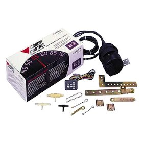
A bit of research on the internet turned up a company that builds cruise controls just for motorcycles. http://www.mccruise.com/ But they are vehicle specific and a bit pricy. Further searching turned up a number of sites where folks were using a particular Audiovox cruise control on their bikes.
- http://www.the12volt.com/cruises/cruises.asp
- http://www.fjr1300.info/howto/audiovox.html
- http://www.morrowmarsh.ca/concours/techpages/cruisecontrol.htm
- http://pionet.net/~mtnbiker/CruiseControl.htm
- http://www.gadgetjq.com/electronic_cruise.htm
- http://www.murphskits.com/avc.htm (updated 12-7-04)
- http://www.fjrowners.ws/forum/messages/2173/4939.html?1049695941 (added 3/13/05)
- http://community.webshots.com/album/228726197ZedVRw (added 3/15/05)
- http://home.comcast.net/~agolder/index.htm This is a great photo site showing how to hook up the linkage.
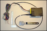
This seemed like the answer. The unit is the Audiovox CCS-100. A search on this unit will turn up a number of on-line vendors with prices ranging from $89.95 to $139.95. I bought mine from JC Whitney www.jcw.com You can also find them on EBay and at Amazon.com
I recently discovered another aftermarket cruise control that does not need vacuum to operate. It is a completely electronic unit. I’ve talked to a few folks that have installed them on their bikes. Sounds like the answer, but they are twice as much money as the unit we are using here. But on some bikes, where space and or vacuum (single cylinder bikes) are a premium, this unit might be the only way to go.
Buy it here: http://www.julianos.com/cruise_control.html
Read up on it here: http://www.rostra.com/
(UPDATE 3-16-06) I understand that Audiovox now has this same unit available without vacuum control. It uses an electric actuator to move the throttle. This might be a better solution for most motorcycles as most motorcycles don’t develop a heck of a lot of vacuum, therefore you need to use a vacuum reservoir. I’m waiting for some feedback from a few folks who are in the process of installing this unit. I’ll update as I get it.) (Update…I bought an electronic version and installed it on my 2007 DL650 V Strom….see below)
The following installation guide is specific to the 2004 Suzuki DL650 V Strom but it would not vary much on just about any other motorcycle out there. If I could find space on the “Wee Strom” to mount the various components, you can find space on any other bike. The V Strom is very space challenged under its various fairings.
Let’s state this right here and now. Be warned, like anything you are attaching to your bike, especially if it is attached to the throttle linkage, if done improperly, or without the highest regard to quality workmanship, it could and just might kill you, passengers, standers-bys, brother-in-laws, small children, deer, democrats and republicans! Don’t you (or most likely your estate) come and sue me because you are a bone head and used spit, bubble gum and a prayer to install your cruise control! I assume no responsibility or liability for anything you do. Got it!
Ok, let’s go, by the way, you will need to look at the pictures at http://public.fotki.com/Rbertalotto/motorcycle/v-strom/ and at http://home.comcast.net/~agolder/index.htm. Rather than include them in this document which would make it quite large.
The steps are really quite simple. Remove fairing, install servo assembly and tie into throttle. Install dash mounted control switch to handle bars. Hook up the wires. Test unit. Go for a ride.
The photographs outline the installation of the various devices better than I can describe them. Something about a picture being worth 1000 words.
Let’s talk about the wiring. You need to locate the following wires.
Tach Drive, Vehicle Speed Sensor/Speedometer (VSS), Brake light feed, Brake on/off, 12V switched, Ground. If you are used to using a $3 test light in your pre 1980 car to find voltage, forget about it on modern vehicles. These “test lights” have way too much resistance and touching the wrong wire can fry your computer, ECM, etc. You need a “reasonable” digital volt meter. Not an analog one. A reasonable DVM can be bought at Radio Shack or other electronic supply stores for well under $50. If you are reading this I would guess you are going to be messing around with the wiring on your bike at some time or other you therefore DESERVE a nice Digital Volt Meter!
On the V Strom we will find these wires in the following locations:
Tach Drive (Blue wire from the Audiovox main unit) attaches to the Brown Wire with a Black Stripe found in the huge connector (Molex connector) under the left front fairing. This connector is used to run all the “chassis” wiring to the “dash board” wiring. Attach your wires to the “chassis” side of the connector. In this way there is one less connector between the Audiovox system and the bike electronics and if you ever needed to remove the entire dash board, it wouldn’t upset the wiring to the CC (cruise control).
VSS (Grey wire from CC main unit) attaches to the Pink wire with a white stripe in the connector listed above. Be aware we are talking about the grey wire from the main unit, not the grey wire from the handlebar mounted control unit. Got it! This grey wire from the main control unit is paired with a black wire. The black wire is not used. Disregard it. This part drove me a bit nuts for a few moments. It’s not spelled out particularly well in the Audiovox installation manual.
Brake Light Feed (Red wire from main control unit) attaches to Orange If you trace the wire coming off of the foot brake switch, you will find it. wire with White stripe wire found in a two wire Molex connector just in front of the fuse box, behind the gas tank under the seat.
Brake ON/OFF (Purple wire from Main Unit) attaches to white/black stripe found in connector above
Ground (Black wire from Main Unit and black wire from control unit) We’re talking two black wires here. One from the main unit and one from the handle bar mounted control unit. Both of these go right to the negative terminal on the battery. Do not attach them to the chassis of the bike. Modern bikes use all kinds of dissimilar metals in their construction and an electrical signal flowing through these metals can start electrolysis and eat your motorcycle right before your eyes.
Main Power (Orange wire with fuse holder attached and the single grey wire from the handle bar mounted control unit) These wires are connected to a switched 12V source. IE: a wire that shows 12V when the ignition key is in the on position and zero volts when the key is off. I attached these wires to my auxiliary fuse box which is controlled via a relay to power up only when the bike was “on” . But you could probe wires to find one. The main feed for the headlights would be a good bet. If you tap into the high or the low beam wire, your cruise control will only work with either the high or low beams on. Be careful.
Ok, so now you’ve got all the wiring done. Now you need to attach the control cable to the throttle. The instructions that come with the unit detail the many ways to do this. You will need to remove the fuel tank on the V- Strom to do this. If you look at the pictures in the photo album, you will see that I went up the right side of the bike with this cable. I attached it to the rear throttle body linkage. This was accomplished by drilling and tapping a very small hole (6-32) in the little stop that hits against the throttle idle adjustment screw. I used one of the cable loops that are supplied in the kit and a stainless steel screw to attach it. I’m sure there are other ways to accomplish this. (See other photo album link above) Just be sure that wherever you attach this control cable that it doesn’t bind. Be especially careful about the secondary linkage that is controlled by the bikes ECM unit. Don’t ask me how I know, but if the screw you use has too big of a head it can bind on this linkage and allow you to pop the coolest wheelie you ever saw when you go to shift into second gear! YEOW!
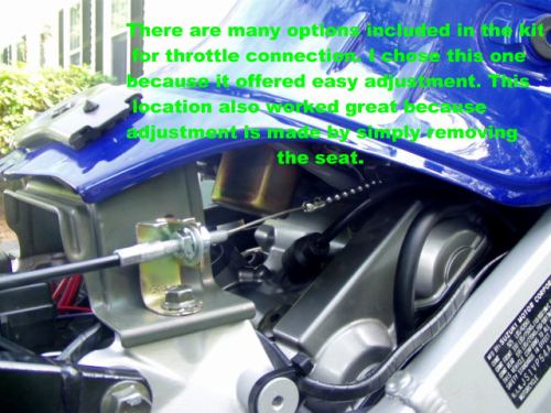
On to the vacuum lines. I used a short piece of vacuum line with a “T” connection to tie both of the throttle bodies together and give me a vacuum line down to the aux vacuum canister. I pulled vacuum off of the throttle bodies at the capped nipples. On my bike, the throttle bodies have two nipples. On the front TB, one of the nipples is used and the other is caped. Remove the cap and attach one end of the hose here. On the rear throttle body, there are two nipples. Both capped. I used the one on the right, standing behind the bike looking forward. I’m not sure if it matters what one you use.
The aux vacuum canister has two nipples on it. One is in, one is out. Connect this hose from the TBs to one of them. They are not clearly marked, we’ll sort this all out later.
Take another piece of hose, connect it to the other nipple and snake it across the bike, in front of the battery to the Servo Assembly Unit. Do not hook it up to the Servo Assembly unit. We need to do some testing first. We’ll get to this later.
Programming the Servo Assembly Unit dip switches is next. Here’s how they are set for the 1000 and 650 V Strom. The installation manual details how to access them and what is on and what is off.
- SW1 – ON – A combination of switch #1 and #2 sets your PPM (Pulse Per Mile)
- SW2 – ON – set to 8000
- SW3 – ON – Speed Signal, set to VSS & TACH
- SW4 – ON – A combination of switch #4 and #5 sets the vehicle power and
- SW5 – OFF – weight,set to LOW – Light vehicle with relative highhorse power
- SW6 – OFF – Control Switch, set to OPEN (the dash mounted control is an OPEN circuit)
- SW7 – OFF – Tach Source Select, set to ECM
You also need to remove the black jumper wire thingy as outlined in the installation manual. This only stays in place if your motorcycle has an automatic transmission.
At this point you want to hook up the Molex connector that goes between the Dash Board Control module and the Servo Assembly unit as outlined in the installation manual, put a fuse in the fuse holder on the orange wire and run the test using the LED in the Servo Assembly Unit as outlined in the instruction manual. If anything is a “no-go”, then check your wiring and your connections. I would suggest all connections either be soldered or use marine grade butt connectors. I wouldn’t use the supplied “Scotch Locks”. They are just a device to drive installers crazy and will fail over time! But, it’s your dime.
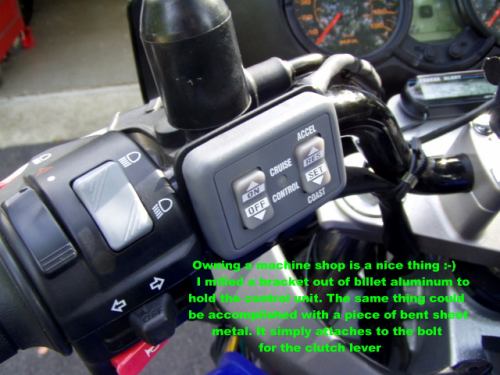
If all your tests are A-OK, then reinstall the gas tank and let’s test the vacuum line. Start the engine. Have your finger on the kill switch just in case the bike starts revving out of control because something bound up in the throttle linkage (don’t ask me how I know this!).
If the bike is idling fine, place your finger over the vacuum hose that you snaked across the bike that will be hooked up to the Servo Assembly unit. You should feel vacuum. If not, reverse the hoses on the aux vacuum canister. The vacuum canister has a “one way valve” and it is not clearly marked Once you feel vacuum, (and by the way, it’s doesn’t feel like much, but I tested it and got 18″ of vacuum, the unit only needs about 9″ to operate properly) connect this hose to the Servo Assembly units vacuum nipple.
DL1000 Owners: It has come to my attention from Mike “Yukon” Palmer that there are some differences between the DL1000 and the DL650. Here is an email I received from Mike outlining the differences.
Hey Roy,
Okay, first is the wiring. On the DL1000 there are “two”molex connectors in the left front fairing. The tach drive (brown/black stripe) and VSS (pink/white stripe) are identical to the DL650. They will be found in one of the two connectors in the left front fairing.
Brake light feed is solid orange wire on one side of the connector and orange/green stripe on the other side (the other wire is white/black stripe on both sides).
I connected the main power (orange wire with fuse holder and single grey wire from handle bar unit) to the mainfeed for the headlights. I found the main feed inside the harness running down the left side of the frame neck. Trace wires from left handlebar control switches for hi-lo/horn and you will find it. Carefully slit open the black covering and look for a yellow/white stripe wire. This should be the main power (switched power) and will show 12v on hi beam and lo beam with the ignition switch”on”.
Make sure you leave enough wire to easily make the connections and so that you can wire tie wires up out of the way for a clean look. These wire colors are the same in the 02, 03 & 04 models according to the wiring schematics.
Now on mounting the servo (main) unit. The only reasonable place I found to mount it is under the right side cover (as you sit on the bike) next to the batter and just behind the brake fluid reservoir for the rear brake. I used hose clamps and padded the unit with foam rubber. I ran the cable forward along the cylinders then looped backward and then again forward over the rear cylinder head. I attached it like John did with a cable clamp using the hex bolt on the rear throttle body.(See photo of JohnofChar’s install http://johnofchar.smugmug.com/gallery/107330).
I used one vacuum nipple from each throttle body which had caps on them (unused). I connected them like you did with a “T” fitting from the CC kit and 2 short lengths of vacuum hose. I then connected a long length of hose (shielded with split plastic protector) to the vacuum chamber.
I mounted the vacuum chamber in the tray under the seat directly behind the batter using double stick foam tape. I drilled 2 holes though the right side of the tray to run the vacuum lines (1 from the servo unit and the other from the “T” fitting). Not a lot of difference, but enough that it could be confusing to a DL1000 owner.”
(UPDATE 8-31-05) On some bikes, pulling in the clutch will not release the cruise control and/or it might take a few seconds for the Audiovox unit to recognize the engine revving it’s guts out before it turns itself off. Neither of which is very safe. We are not sure why this happens on some bikes and not others. In any event a V Stromer came up with a very nice solution. And it also allows you to hook up tail light flashers and other taillight devices that otherwise confused the Audiovox unit. His design uses the electrical switch on the clutch lever to break the circuit and a relay to create a “fake” brake circuit. His letter to me is below:
Roy: It’s just like magic. I re-jigged the two relays on the clutch and brake circuits to break a ground circuit and isolate the cruise control from the brake light circuit proper and voila! I have a very polite cruise control system. It now shuts off instantly on clutch or brake application and the brake lights are just brake lights.
Here’s the code: 2 SPDT (5 pin) relays
Clutch relay:
- 30 to 87A of brake relay
- 85 to 12V I used an auxiliary circuit here but the red wire should work too.
- 86 to black / yellow on starter relay (right in front of battery) This is the switched ground from the clutch lever.
- 87A to 30 to ground ( this goes in series with the other relay to the purple cruise control brake signal wire)
Brake relay:
- 30 to cruise control purple wire
- 85 to ground
- 86 to the brake signal wire
- 87A to 30 of the clutch relay.
The ground circuit that goes through both relays in series is broken by either lever and the brake circuit does not touch the cruise control module. You should be able to reconnect your other taillight accessories after this modification
Regards,
Greg H.
THANKS GREG!
(UPDATE 2-24-06) A Mr. Ron Abbott recently sent me another method to accomplish what Greg suggested but uses a single relay. Both methods will work fine. Send me an email requesting Ron’s write up and I’ll email it to you.
THANKS RON!
That’s it, you’re ready for a test ride. Move your handle bars side to side and test the brake and clutch cable to be absolutely sure nothing is binding or inhibiting the function of these controls.
Put on all your gear!
If something goes wrong and you lose control, now is the time to test your riding gear!
Use the test procedure outlined in the installation manual on your test ride.
Everything should work. If it doesn’t here are a few things to look for.
If you have any type of aftermarket brake light flash unit installed on your bike, and did not install Greg’s double relay circuit, remove it (Or install the relays as outlined above). The Signal Dynamics “Back Off” unit and certain LED brake lights will render the Cruise Control inoperative. I’m not sure about other devices, but I know for sure these units are a no-no.
Check your wiring again. As you bundled up your wires for your test run, you might have pulled something loose.
A couple of thing you might want to be aware of. If after you install the unit, and test drive the bike, you may experience backfiring when you close the throttle. My bike did this and it turned out I had the cruise control cable adjusted too tight and the throttle wasn’t closing down completely. I put a bit of slack in the line and everything is fine.
You can not have anything in the brake power circuit. As stated earlier, the Signal Dynamics “Back Off” unit caused the cruise control to not function. I tried to hook up a Kisan Signal Minder (this is a unit that cancels the turn signals after a predetermined number of flashes). It worked fine until I tried to hook up the “Brake Override” function, which ties into the brake line. Not only would the signal minder not work, but the cruise control stopped working also. The Flash Cancel still works, but the brake override does not.
If it still doesn’t work, call the Audiovox Help Line number in the installation manual. They are extremely helpful.
So, that’s it. Enjoy your new Cruise Control, just don’t fall asleep!
A NEW “ELECTRONIC VERSION†IS NOW AVAILABLE!!!!!
I recently found out about a new “non-vacuum†electronic version of the Audiovox CC-100 cruise control. It’s made by Rostra (these are the folks that make all of the Audiovox units and most OEM cruise controls for the various auto manufacturers).
The unit is Rostra #250-1223 Global Electronic Cruise Control…$165 available from Brandon Distributing Inc http://www.brandondist.com/
http://www.brandondist.com/products/cruise1223.htm
There are two versions….With and without engagement light on the dash mounted controller. Save a few $$, you don’t need the engagement light. You can’t see it in the light anyways.
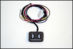
I recently finished installing this new electronic unit on my 2007 Suzuki V Strom…….More Better! Much smoother operation, never loses vacuum and slows down going up long hills. Same wiring as the vacuum unit, but no tubing and vacuum canister.
I ended up mounting it under the rear seat, because the 07 V Strom has ABS and the space I normally would use was occupied by ABS stuff. It fit great just in front of the tail light assembly and was very easy to install. I highly recommend spending the extra $40 for this unit.
Folks have asked where I put the dip switch settings on my new Electronic Unit
Here is where I have them set:
1-OFF
2-OFF
3-ON
4-ON
5-OFF
6-OFF
7-ON
8-ON
9-ON
10-ON
11-OFF
12-OFF
Hope this helps
PS…Send me an email and I’ll send you a Word Doc with these installation instructions and a few more hints on using relays to activate and deactivate the cruise control
ADVERTISEMENT:
This web site is part of my income stream. If this article was helpful
to you, you might want to throw a few bucks at me via paypal
rvb100@comcast.net
Not necessary, but certainly appreciated!
If you have any questions, I can always be reached at rvb100@comcast.net
Thanks
RoyB

Pingback: so greywolf whats it like ? - Page 10 - Stromtrooper Forum : Suzuki V-Strom Motorcycle Forums
Pingback: Add-on Cruise-Control? - Honda Shadow Forums : Shadow Motorcycle Forum
Pingback: Cruise Control - Honda Goldwing Forums
Pingback: New Member - Suzuki GSXS1000 Forum