
Recently I aquired a PASS LABS First Watt F5v2 stereo amplifier to add to one of my systems
You can read all about that experience here:
http://rvbprecision.com/stereo/nelson-pass-first-watt-f5-turbo-v2.html
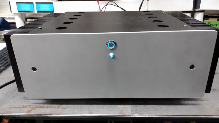
Although I cleaned it up and installed a front mounted power switch and an LED indicator light, I wanted to modify it a bit more by adding VU meters to the front panel.
I decided to go with McIntosh looking, blue, square meters. A search on Ebay turned up exactly what I was looking for:
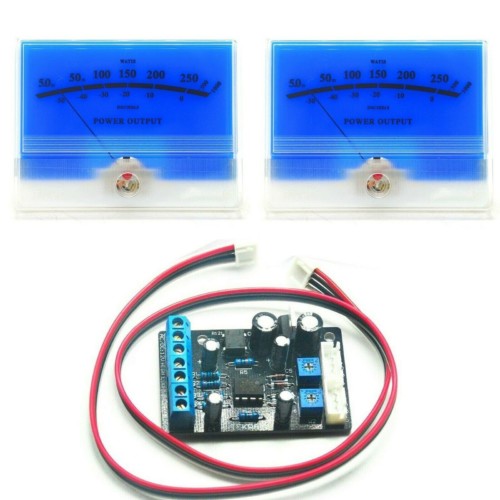
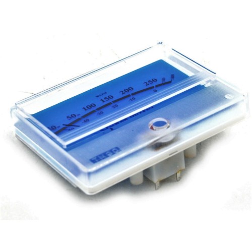
2x McIntosh Classic Blue Panel VU Meter DB Audio Power Amplifier w/ Driver Board
(UPC:6476442119053)
Here are the specs for the meters if you can’t find the exact units I used:
VU Meter Parameters:*Size: see the product picture;*Pointer material: zinc white copper*Pointer color: black*Pointer swing direction: from left to right*Pointer length: from the central axis to the needle end 44±1mm*Pointer width: 0.45 ± 0.05 mm*Meter use direction: vertical*Current sensitivity: 960uA±8%*Internal impedance: 650? ± 10%*Use / storage temperature limit: -10 ° C to +60 ° C RH 35 to 85%

These meters were shipped from China and took weeks to arrive… 🙁
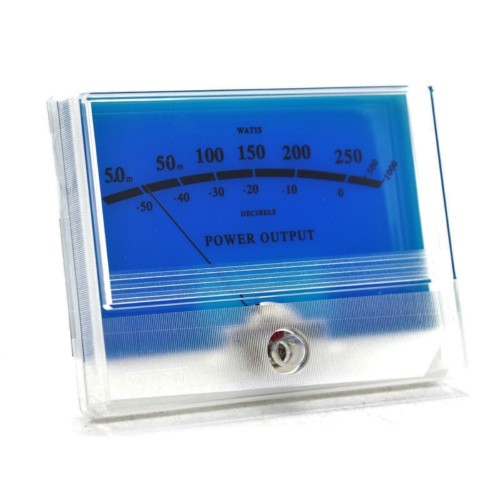
I love that the say “WATIS” rather than WATTS
Once I had the meters in hand, I used my milling machine to cut accurate square holes into the aluminum face plate. Yes, I know, not everyone has a milling machine at their disposal. But a saber saw, with a metal blade and some WD40 as cutting oil will do a great job. Cut the hole a bit smaller and finish it up with a file. Cut from the back of the faceplate. (Or you could purchase round meters that just require a hole saw to mount)
(NOTICE…I didn’t build this amplifier. I bought it assembled. The builder or the manufacturer of the face plate has the two mounting holes just slightly off center. I used my Digital Read Out on my milling machine and took all measurements from the center of the panel, not realizing the holes were not the same distance from each end and now one is closer to the VU meter than the other…This is driving my OCD crazy!….UGH!)
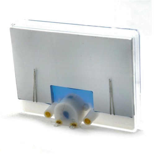
So now the panel is cut. I need to figure out some way to hold the meters in place.
I decided to secure them from the rear with a simple aluminum bracket, held in place by the main power switch.
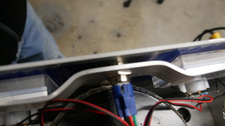

This worked out great!
Now to wire them up.
The meter driver board that the meters came with had no instructions but did caution that a resistor would be needed across the LED lights if I was going to drive the board with 12-18V AC or DC. I sent an email to China to inquire about this and I was told there is a new, improved driver board available that does not need the resistor and has more control over the action of the meters and the LEDs would now be dimmable. They offered me a substantial discount so I ordered the new board.
This is the original board:
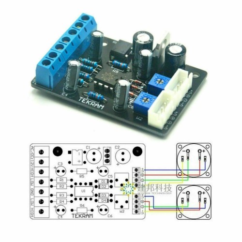
And this is the new improved board:
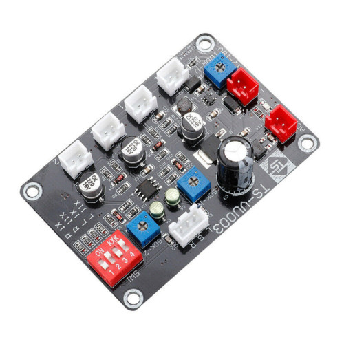
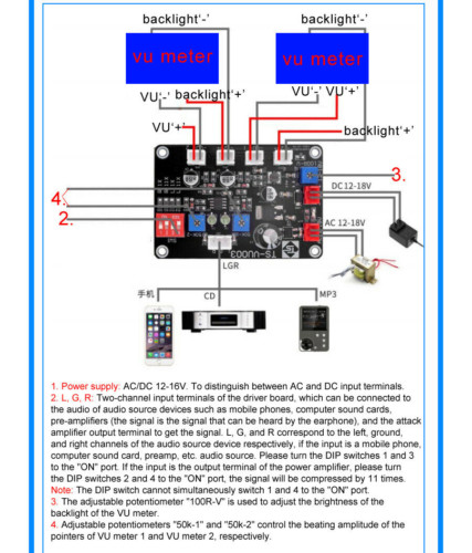
This new board came with great instructions on the setting of the DIP switches and other things you might need to know.
But not wanting to wait for the “Slow Boat From China”, I installed the old board just to see how the meters would look.
I used 330ohm resistors across the VU meters LEDs and the brightness was perfect!
As it turned out, the replacement board showed up in just a couple days! Go figure..
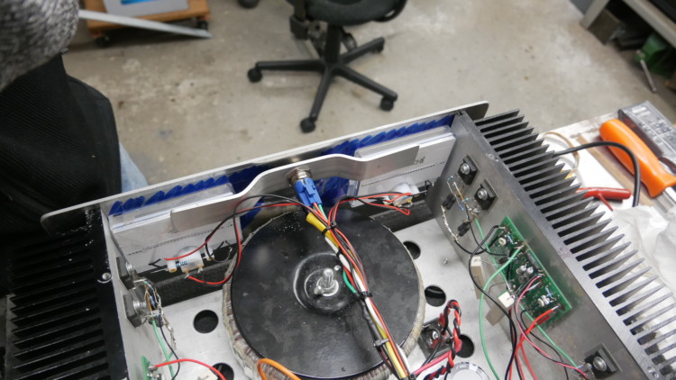
The board was mounted to the inside back panel of the amplifier using plastic stand-offs
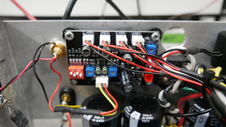
and wire was run from the low level inputs to the board, and from the board to the meters.
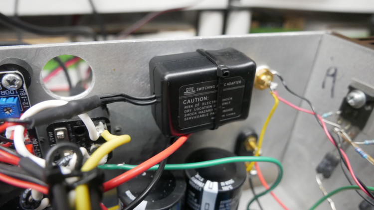
I needed to find 12V, either AC or DC somewhere in the amplifier. But in the end I decided to add a small 12DC power supply that I had in my junk box. This was mounted to the inside back panel also. (More about this later)
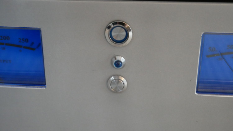
I wanted to be able to deactivate the meters if the light and movement became distracting so I drilled another hole in the faceplate and mounted a push button power switch to cut power to the 12V power supply
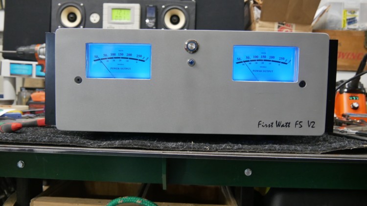
With that, I was done! The meters work great. Using a Sound Pressure Level Meter, I set “0” VU at 90dB as I usually listen at 75dB and this setting give a nice deflection of the meters.
Be aware, these meters really show nothing meaningful. They are just a nice visual and something to impress your brother-in-law !
Video of meters in action:
UPDATE:
Listening to the amplifier using a Schiit Freya preamplifier being fed from a Node2i streamer through a Gustard X16 DAC, I think I’m hearing a tiny bit of shrill in the upper frequencies that I don’t hear when I shut the meters power supply off. Could be psychoacoustics.
COURSE OF ACTION: I decided to replace the power supply with a known low noise unit and I’m going to mount it away from the amplifier.
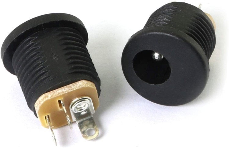
I’ll install a 5.5 x 2.1mm DC Power Female Jack on the rear panel to allow easy disconnect of this new power supply.
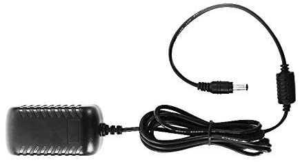
This is the remote power supply I’ll be using. It has been getting all the rave reviews:
iFi iPower – Low Noise DC Power Supply 12V/1.8A
Active Noise Cancellation+ (ANC+)
“By generating a signal identical to the noise signal but in the exact opposite phase, it actively cancels all the incoming noise. ANC+ is the perfect ‘antidote’ for power supply noise, the bane of USB audio. With ANC+ the power line is filtered for audio band and RF noise. The measured noise floor of 1uV (0.000001V) is at the measurement limit of what even the most sophisticated Audio Precision equipment is capable of.“
I’ll also try running the driver board off the speaker outputs as I now have it running off the low level preamplifier inputs. This board can be connected either way.
So, while waiting for the new power supply to arrive I’ll enjoy the amplifier as I have it presently configured.
Stand By for a future update!
Be sure to check out other articles I’ve written on my web page
Thank You!
Pingback: ICE Power Amplifier Build | RVB Precision