I recently became involved in casting my own bullets out of lead. To accomplish this, one uses an electric furnace to melt the lead alloy and keep it in a molten state. For best performance, it is important to keep the temperature of the molten lead at a steady temperature. Plus or minus 15 degrees from 750 degrees would be ideal. But as the lead is used and the quantity is deminished, the temperature can raise wildly.
The answer is some way to electronically control the electricity to the furnace to maintain a constant temperature. This is where a PID comes in. proportional–integral–derivative controller, nice set of words. What it means is:
According to Wikipedia:
A proportional–integral–derivative controller (PID controller) is a generic control loop feedback mechanism (controller) widely used in industrial control systems – a PID is the most commonly used feedback controller. A PID controller calculates an “error” value as the difference between a measured process variable and a desired setpoint. The controller attempts to minimize the error by adjusting the process control inputs.
The PID controller calculation (algorithm) involves three separate constant parameters, and is accordingly sometimes called three-term control: the proportional, the integral and derivative values, denoted P, I, and D. Heuristically, these values can be interpreted in terms of time: P depends on the present error, I on the accumulation of past errors, and D is a prediction of future errors, based on current rate of change.[1] The weighted sum of these three actions is used to adjust the process via a control element such as the position of a control valve or the power supply of a heating element.
In the absence of knowledge of the underlying process, a PID controller is the best controller.[2] By tuning the three parameters in the PID controller algorithm, the controller can provide control action designed for specific process requirements. The response of the controller can be described in terms of the responsiveness of the controller to an error, the degree to which the controller overshoots the setpoint and the degree of system oscillation. Note that the use of the PID algorithm for control does not guarantee optimal control of the system or system stability.
Simply put, it is a computer that reads the temperature of the lead with a remote mounted probe and turns the electricity to the furnace on and off as needed to maintain this temperature. Simple !
Let’s start with what the finished unit loooks like
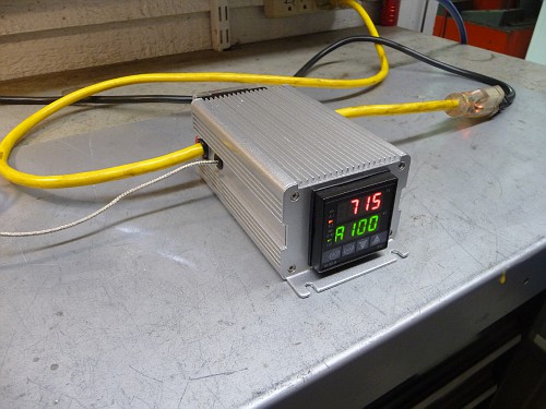
All parts were sourced from Auberins Supply ( www.auberins.com )
(1) PID Temperature controller, DIN, SSR Control Output, #SYL-2352 = $44.50
(1) Solid State Relay SSR, # RS1A40D25 = $15
(1) Aluminum project box, #CPTbox16 = $22.32
(1) K type High Temp Probe #WRNK-191 = $21.62
All prices as of June 2011
The project box comes with the hole already cut to receive the PID control unit.
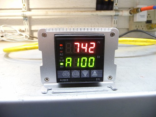
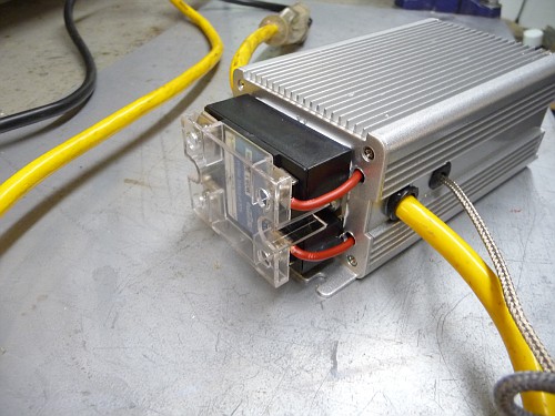
On the rear of the box you mount the SSR (relay)
Holes are drilled for power in and out and for the temperature probe.
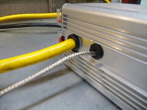
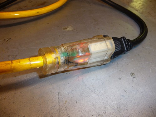
I used an extension cord that has a small led in the female end that shows current is flowing. I cut the cord using about 12″ with the male plug and 36″ with the female.
The PID plugs into a wall outlet and your lead furnace plugs into the PID’s female socket. The rheostat on the lead furnace is turned up to full. You input the temperature you want the molten lead to remain at and how much temperature variation you allow to each side. There are dozens of other parameters you can input, including alarms that sound if temperatures are above or below specified, timers, etc. But for our use we keep it simple and just use the above parameters.
Wiring is very simple. The relay is a simple switch. Current from your wall socket enters at one side and is simply turned on and off as needed by the PID. So 120 Volts in, 120 volts out and two control wires from the PID. Two wires from the temperature probe and you are finished.
Wiring instructions are included with the PID and more can be found with a search on the Cast Boolit Forum. Â Â http://castboolits.gunloads.com/index.php
I hope you enjoyed this little article. Be sure to visit my web site for more articles and visit the photo album.
UPDATE……
A fellow over on the castbullet forum posted a few very helpful links:
PID Wiring diagram
A list of links for various parts:
Parts List For PID Controller
The actual PID Controller – Auber Instruments Best Quality
http://www.ebay.com/itm/200579429664…84.m1423.l2649The K Type submersible thermocouple
http://www.ebay.com/itm/220871428892…84.m1423.l264940amp Solid State Relay
http://www.ebay.com/itm/Lot-2-CRYDOM…item416f81faacHeat Sink for 40 amp SSR
http://www.ebay.com/itm/Heatsink-hea…item35b4c94806Project box
http://www.ebay.com/sch/i.html?_from…ect+box&_sop=7fuse holder
http://www.allelectronics.com/make-a…ST-ALCO/1.htmlfuses
http://www.allelectronics.com/make-a…MA-FUSE/1.htmlindicator lamps
http://www.allelectronics.com/make-a…AMP-RED/1.htmlswitches
http://www.allelectronics.com/make-a…-SWITCH/1.htmlterminal strip
http://www.allelectronics.com/make-a…-20-AMP/1.htmlPower cord ( cut in half for power in and power out)
http://www.allelectronics.com/make-a…RD-14/3/1.html
Thanks
RoyB

Pingback: PID controller parts list