
I have a JET 12 X 36 BD lathe of 1985 vintage. It a wonderful lathe for the type of work I do. Mostly hobby gunsmithing and making various parts for motorcycles and expedition vehicles. When I bought the lathe in 1995 it was box stock. It had been used in the Borden Pasta factory maintenance department in Boston Massachusetts and had been used very little. I had modified the following:
Replaced AC motor with a variable speed DC motor
http://rvbprecision.com/garage-entertainment/machines-in-the-shop.html
Photos of the conversion here:
http://public.fotki.com/Rbertalotto/machine_tool/jet-1236-dc-motor-c/
Added Shooting Star Digital Readout (DRO)
Added an “outboard” spider to the headend
All of this can be seen in a short video here:
http://public.fotki.com/Rbertalotto/machine_tool/jet-1236-dc-motor-c/pc290016.html
(if this link doesn’t work, it is on YouTube):
So now I had a very nice, smooth running lathe. But it was extremely noisy when the gearbox was brought into play to use automatic slide and cross slide feed when turning stock. Also, now that the lathe has Variable DC drive, I can easily change the RPMs of the chuck with a simple twist of a knob. But this also speeds up or slows down the carriage as it is connected to the main spindle by gears. By adding a separate variable speed motor to the carriage drive, I could control spindle RPM and feed independently. Research is needed!
The internet led me in the correct direction. Lots of folks are modifying their mini -lathes with this addition as most mini-lathes do not have any type of automatic carriage feed.
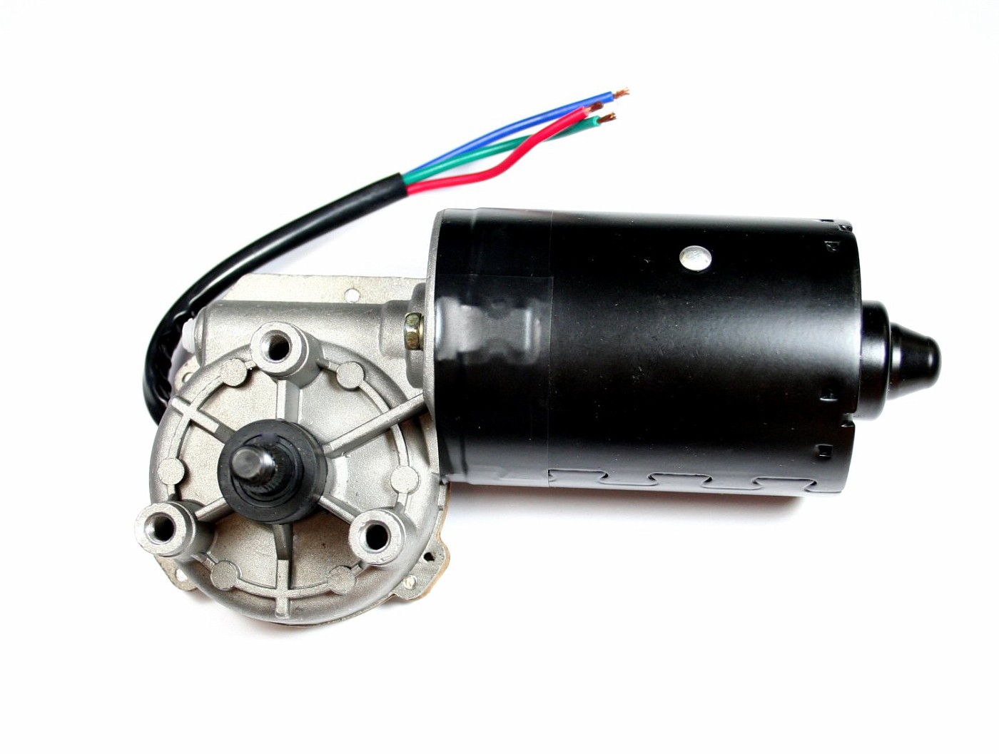
First I need a high torque, low RPM DC gear motor to turn the feed shaft.
Research led me to this motor available on Ebay and at Amazon.com.
http://www.amazon.com/gp/product/B00MVAT95Y/ref=oh_aui_detailpage_o02_s00?ie=UTF8&psc=1
Product Features
|
$55.00 with free shipping from AMAZON. (I ordered it on Friday morning and received it on Saturday……During Christmas week!)
This motor was used to power windshield wipers on motorhomes. Huge windshield wipers! and it was designed for constant duty and it is designed to be reversible. Lots of DC treadmill motors and windshield motors that might be considered in this type of application have the brushes in a particular position that they shouldn’t be run in reverse.
A really neat added feature is the two speed it offers. Very nice!
DC motors need some type of control to make them variable speed. I decided to use this unit as it was highly recommended by others that have applied similar modifications.
It is also available on Ebay and AMAZON.com for a whopping $11.00! Â Believe it or not. This was also ordered from AMAZON on Friday and the USPS delivered it to my house on SUNDAY!!! I couldn’t believe it when the post-person knocked on my door on Sunday afternoon with a package. All for $11 and no charge for shipping. How can AMAZON do that?
http://www.amazon.com/gp/product/B00HTZ5OS2/ref=oh_aui_detailpage_o04_s00?ie=UTF8&psc=1
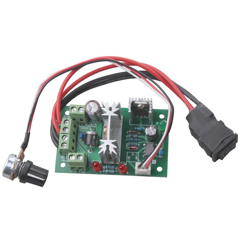
- The input voltage:6V-30VDC
- The maximum output power: 200W (more than 24V)
- The maximum continuous output current : 10A;(DC motor is recommended for use in 6A)
- PWM Frequency: 16KHZ
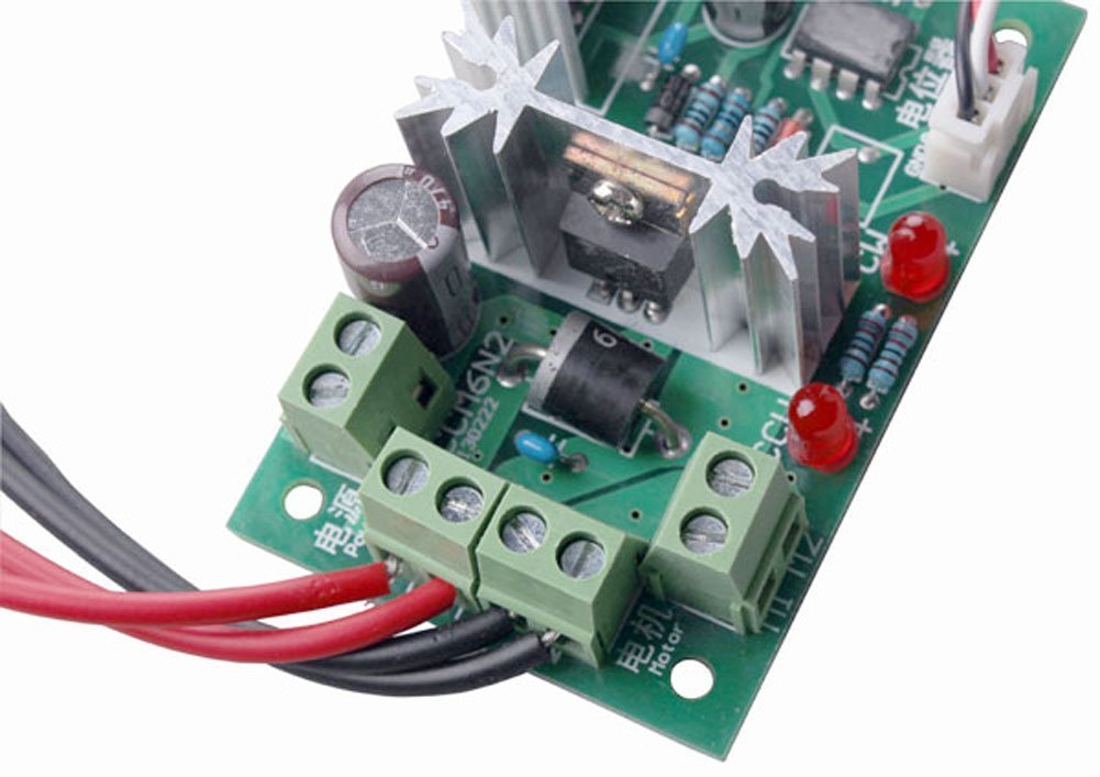
It comes prewired with a potentiometer  and a “forward – off – reverse” switch. I didn’t like the type of F-O-R switch they had wired so I replaced it a as you’ll see. This is an excellent controller for the money. It also offers two LEDs that could be removed (de-solder) from the circuit board and located to the control panel if you like. One indicates forward and the other reverse.
Extremely well made with nice, robust screw terminals for 12V power and motor connections
To power all this, I needed a 12V power supply. Â Something outputting 12V with 6amps should do the trick. This computer type power supply got the nod:
http://www.amazon.com/gp/product/B003TUMDWG/ref=oh_aui_detailpage_o03_s00?ie=UTF8&psc=1
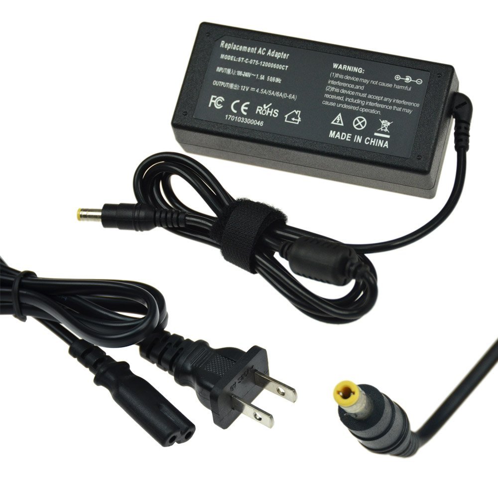
AC Power Supply Adapter DC 12 Volt 6 Amp. From AMAZON.com for $8.69……This unit was again highly recommended by other folks on the internet for this application.
OK….So now I got a bunch of stuff in my shop. How do I make it all work.
Belts….Gears….Direct Drive ????
Direct Drive is out as I want to be able to de-couple the motor from the drive shaft so I can use the lathes gear box if I ever wanted to.
V-Belts and pulleys would be fine and toothed belts and toothed pulleys would even be better. You don’t want something slipping when you are doing a final turn on a critical part.
But I had a few cut metal gears hanging around that I thought would work out the best.
Looking through my “junk” box, I found a gear change mechanism that came with my lathe when I bought it nearly 20 years ago. I believe it is for metric threading or might be simply a replacement part. I have no idea. Since I haven’t had a need for it in 20 years, I figured I’d use it in this project.
Here is what it’s sister piece looks like on the lathe:
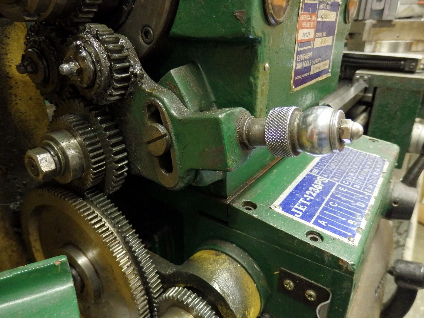
Here, it is being used to change the direction of the carriage feed and screw shaft with the lathes gear box. The knob is spring loaded. Pull it out, move it up or down, release the knob and it locks into position.
In my modification, I’m going to attach a gear to the motor and the motor to this change gear device. I’ll use the whole device to engage a gear mounted on the lathe’s carriage drive shaft.
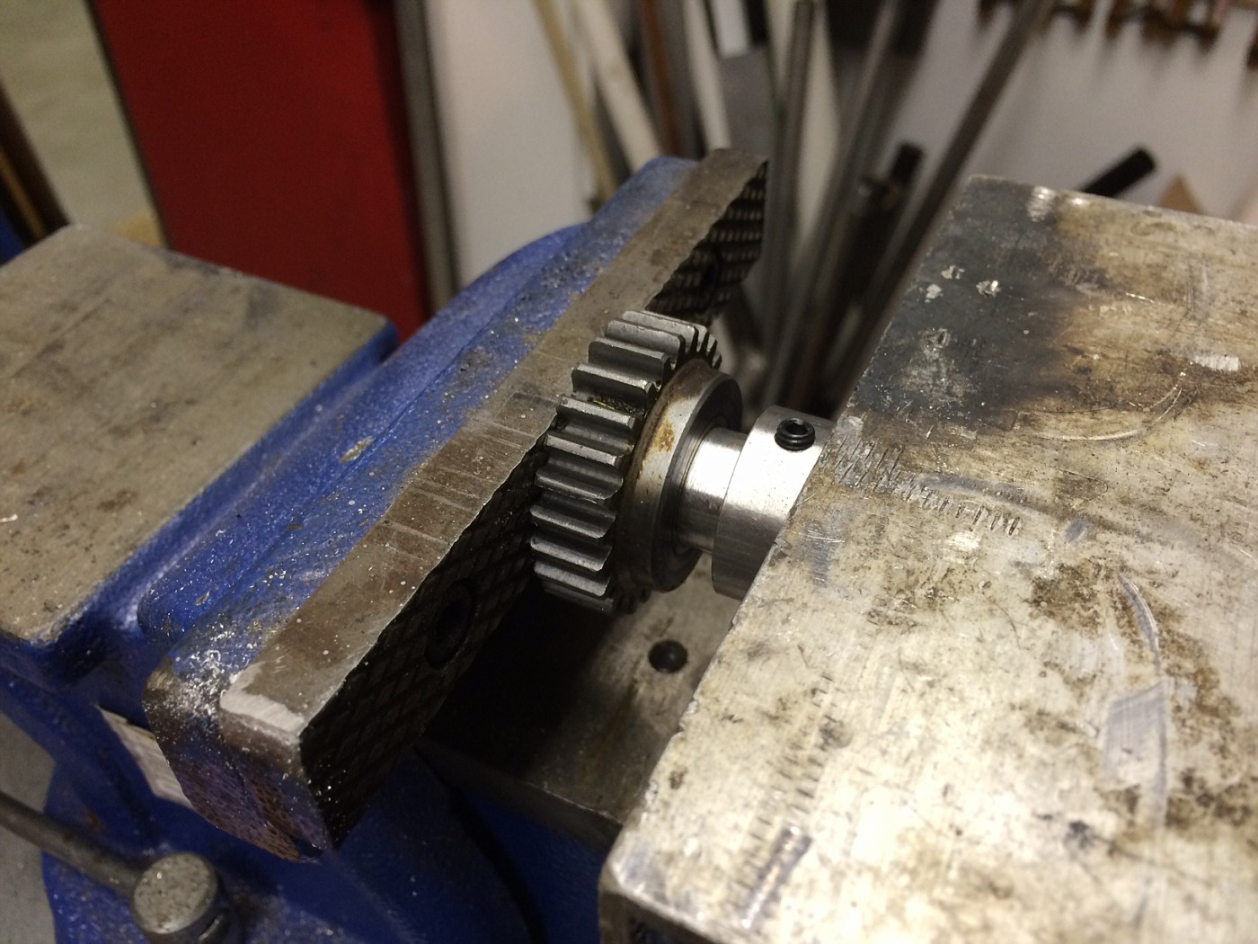
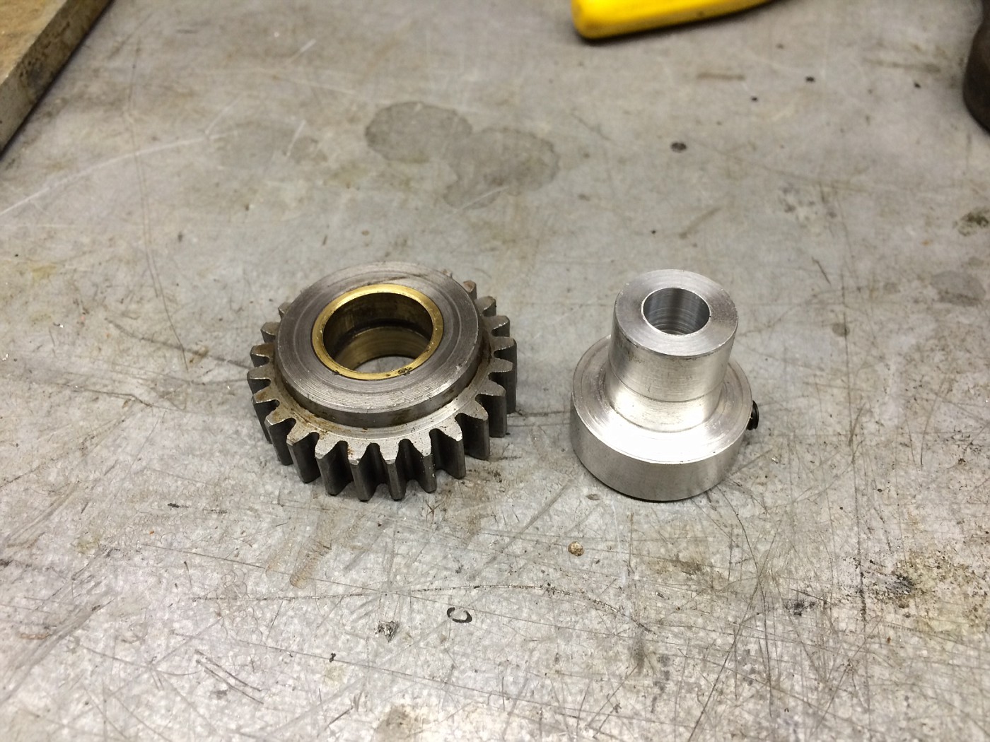
First I needed to turn an adapter to attach a gear to the lathe’s shaft.
An adapter was turned to fit the shaft that extended about a 3/4″ beyond the edge of the lathe. A set screw will hold this gear to the shaft. Should something jam up the works, this will be the only place where slip will be afforded. The adaper was press fit into the gear, that was heated a bit with a 1500 watt heat gun.
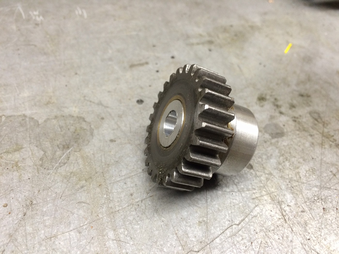
The finished product before attaching to lathe:
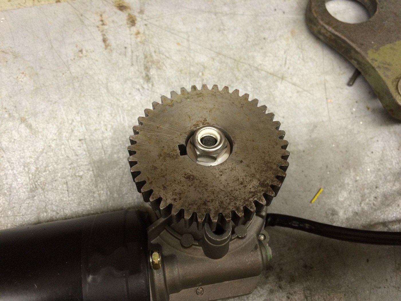
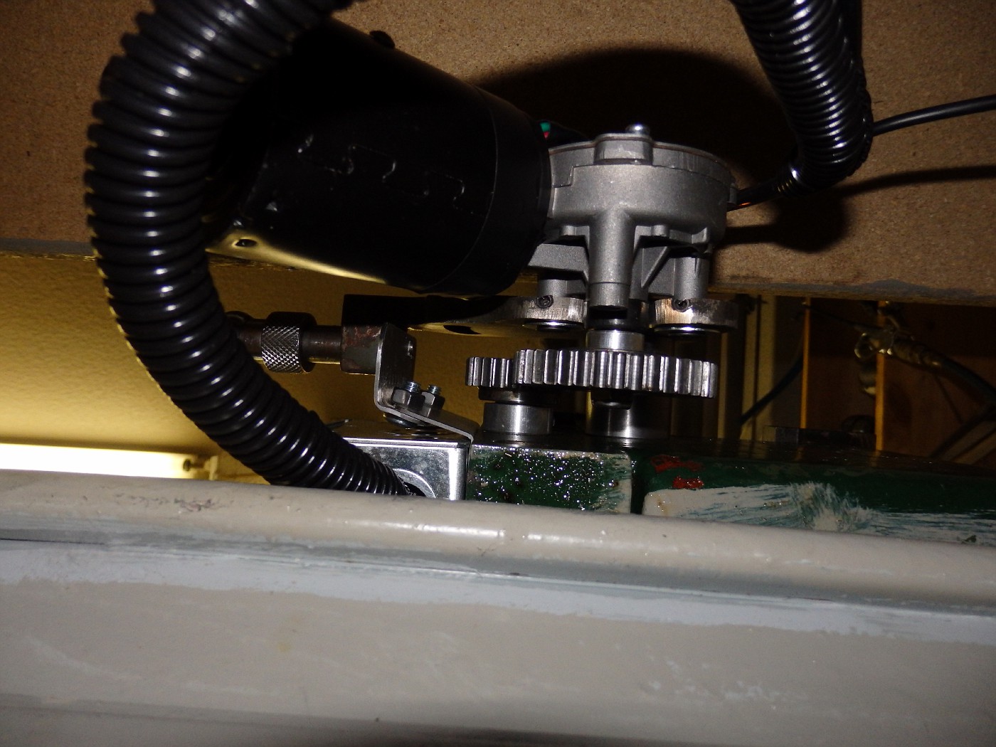
An adapter was turned to attach another gear to the shaft of the motor, and installed.
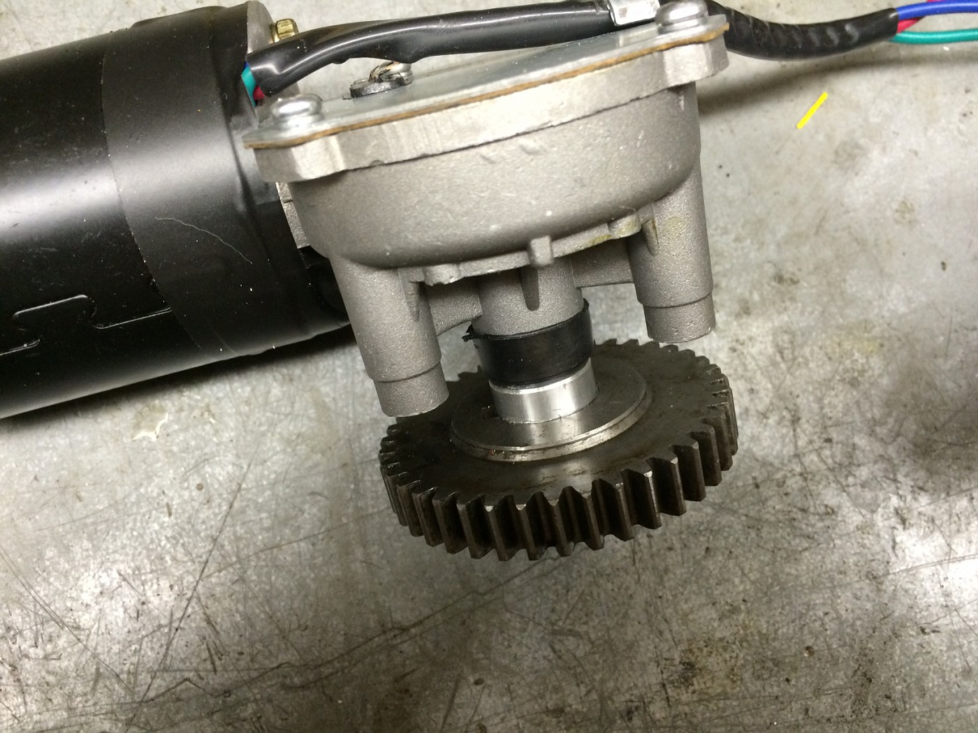
The shaft on the motor is tapered. A simple nylock nut holds it in place:
The gear change device was heavily modified. Since the application would be totally different for each lathe, I won’t go into major detail here. I turned slightly oversized plugs for the two holes that existed for the previous gear train. Pressed them into place  and drilled new holes to secure the DC gear motor. I then milled the whole device down as it was too thick to fit between the motor housing and the gear.
I turned a large stand off / bushing from a piece of stainless steel , and drilled and tapped the side of the lathe for a 3/8 – 20 bolt and attached the gear disconnect in the appropriate place.
The whole motor mechanism rotates on that large standoff / bushing.
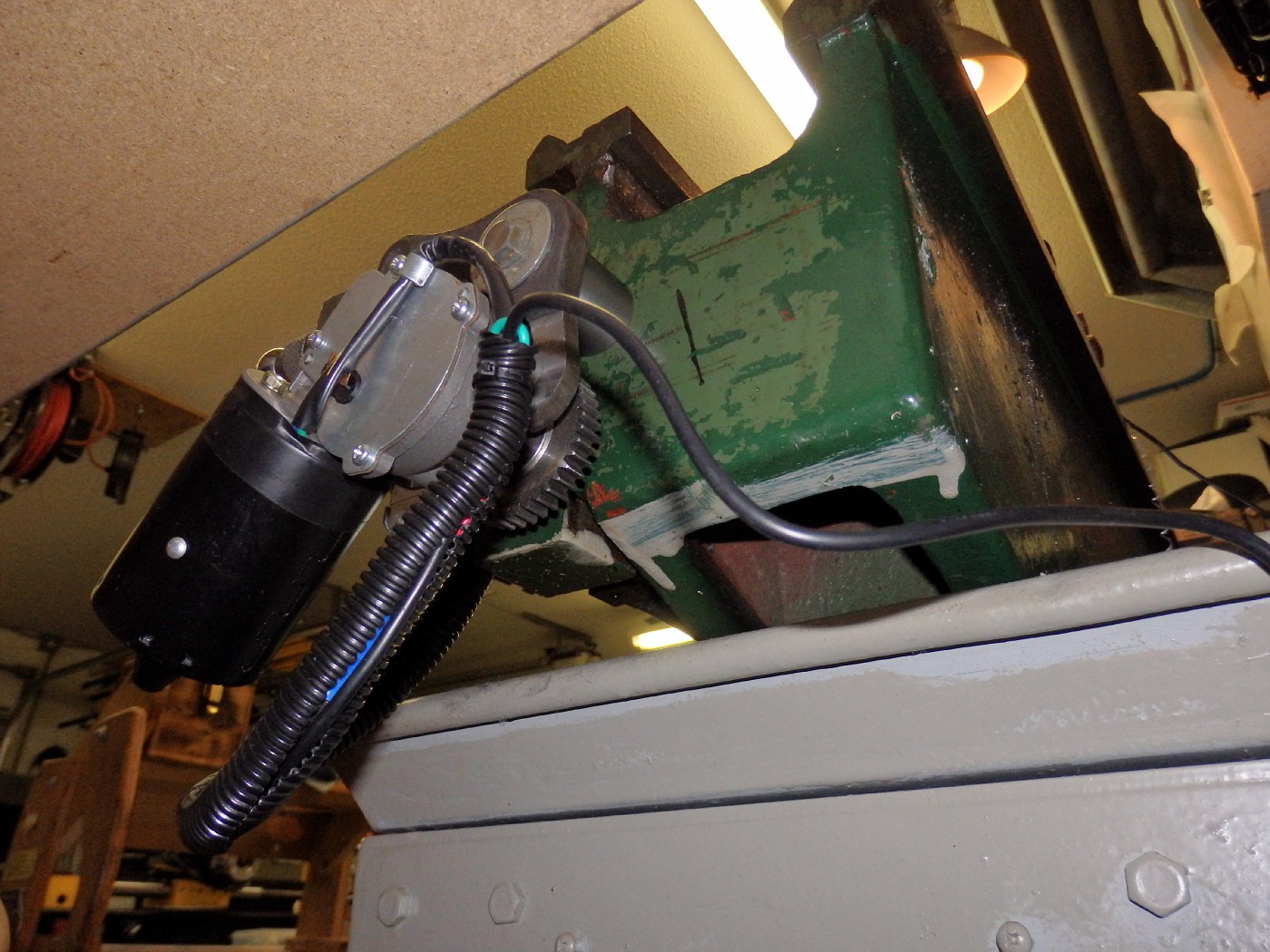
Below is a view from the bottom…
If fit beautifully!
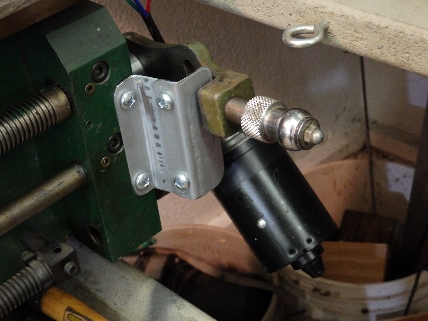
I then bent a couple pieces of metal to make the panel the spring loaded handle locks into. Drilled and tapped the lathe for two 1/4-20 bolts. And drilled a hole for the lock.
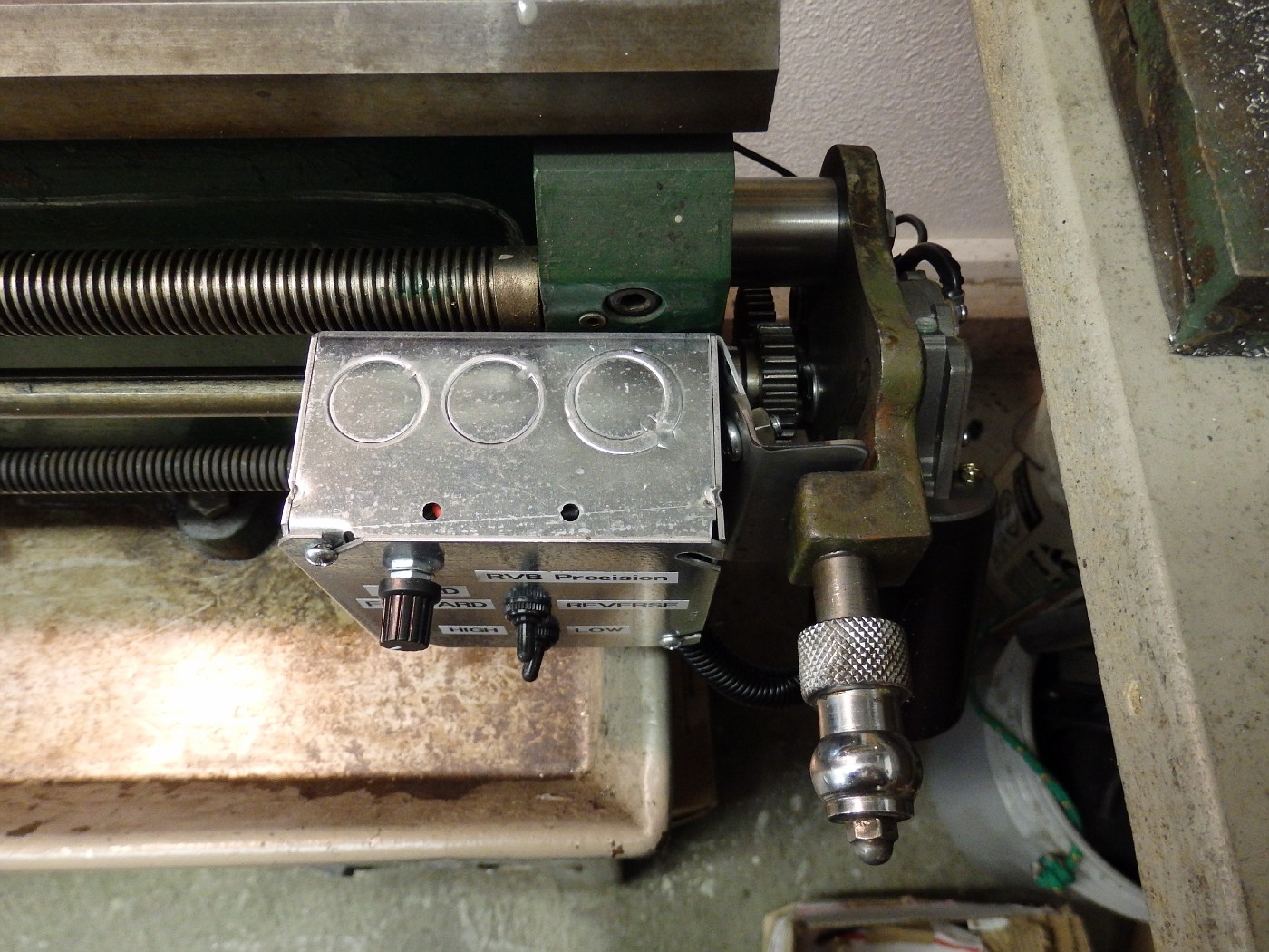
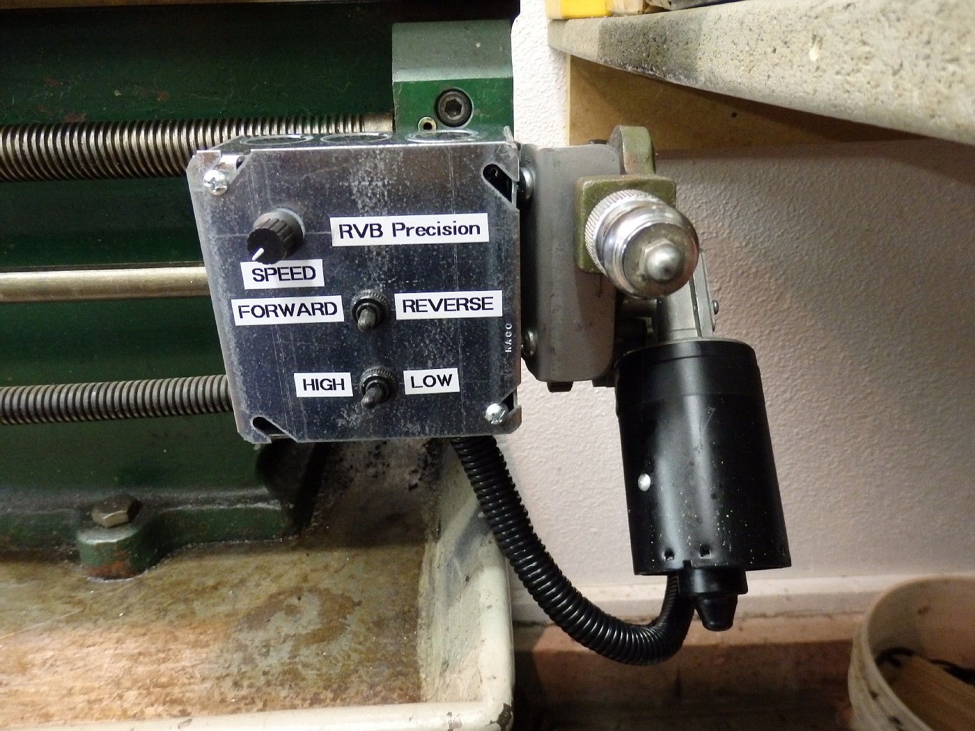
And finally attached the control box.

Lets back up a bit and discuss the wiring.
As you can see, I used, rubber booted, weatherproof (cutting fluid proof) mini toggle switches for both forward and reverse and fore high and low speed. I like these little switches as they are hard to accidently hit, hold up well in a machine shop environment and you can see at a glance where they are positioned. I’ve used them in other application in a similar fashion and they have stood up well for years.
The wiring is quite straight forward.

Although, be aware. The motor and the control board come with ZERO instructions! The board is marked where power and motor are connected. But the motor simply has three wires hanging out of it.
Red – Green – Blue….Red is common hot and green is low speed and blue is high speed.l I used a simple double pole / double throw switch to wire this feature up. The F-O-R switch is anothe DPDT switch. I just transfered the wires fron the supplied switch to my switch. Piece of cake!
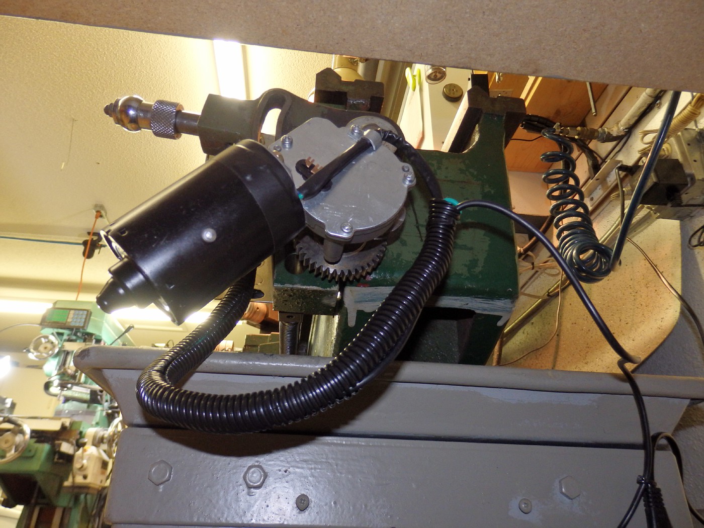
Buttoned it all up, turned it on, and it worked the balls!
Huge power. Can not stall it no matter how large a cut I try to take. Extremely quiet. Barely can hear the motor running even with the main lathe motor off. The variable speed on the lead screw allows some fantastic surface finishes as you can dial it in as the work is progressing. NICE!
Here is a video of it in action:
http://public.fotki.com/Rbertalotto/machine_tool/metal-lathe-power-f/pc290017.html
Lots more pictures of this installation and other projects here:
http://public.fotki.com/Rbertalotto/machine_tool/
I hope you enjoyed this little project as much as I did putting it together.
THANKS for looking!
UPDATE…January 1, 2015
I prepared a nice venison Pot Roast and it is now in the pressure cooker so I have a few minutes to kill. I decided to add a few LEDs to the control panel.
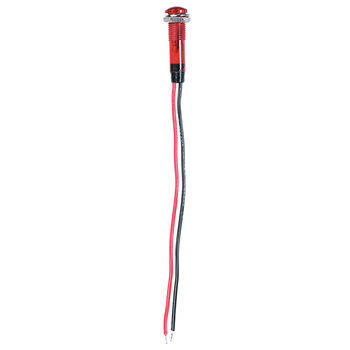
The circuit board has three LEDs mounted. I de-soldered them and replaced with panel mount LEDs I sourced from Radio Shack.
Panel Mount LED with built in resistor – 12V
Part # 276-0270, 276-0271, 276-0272…I chose Red, Green and Orange. They have many different colors to satisfy your artistic bent!
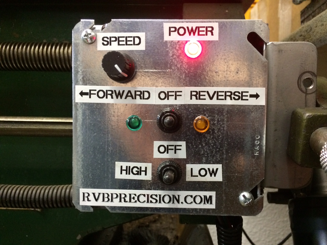
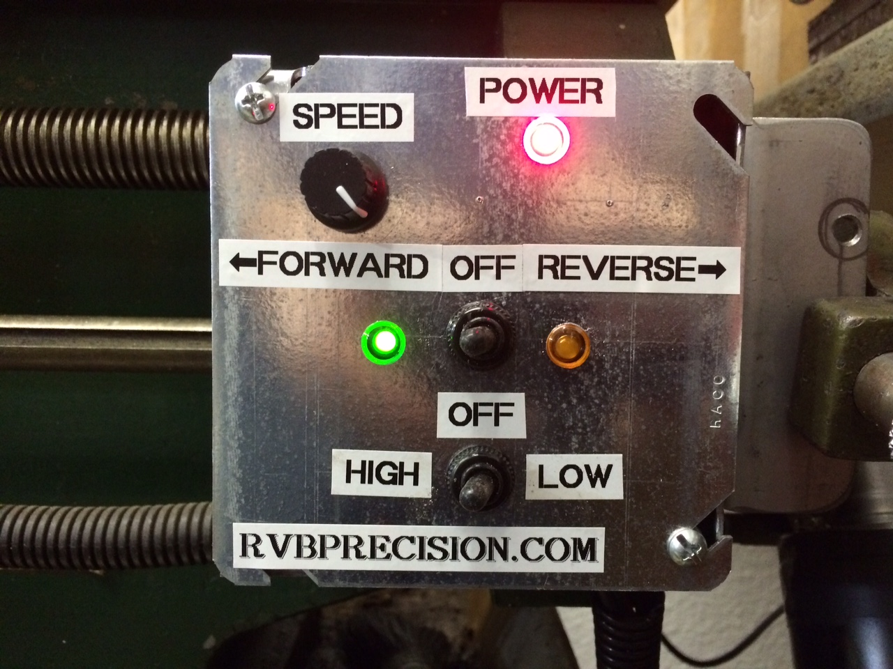
I used a RED LED for simple “POWER”, a GREEN LED for “FORWARD” and an ORANGE LED for “REVERSE”
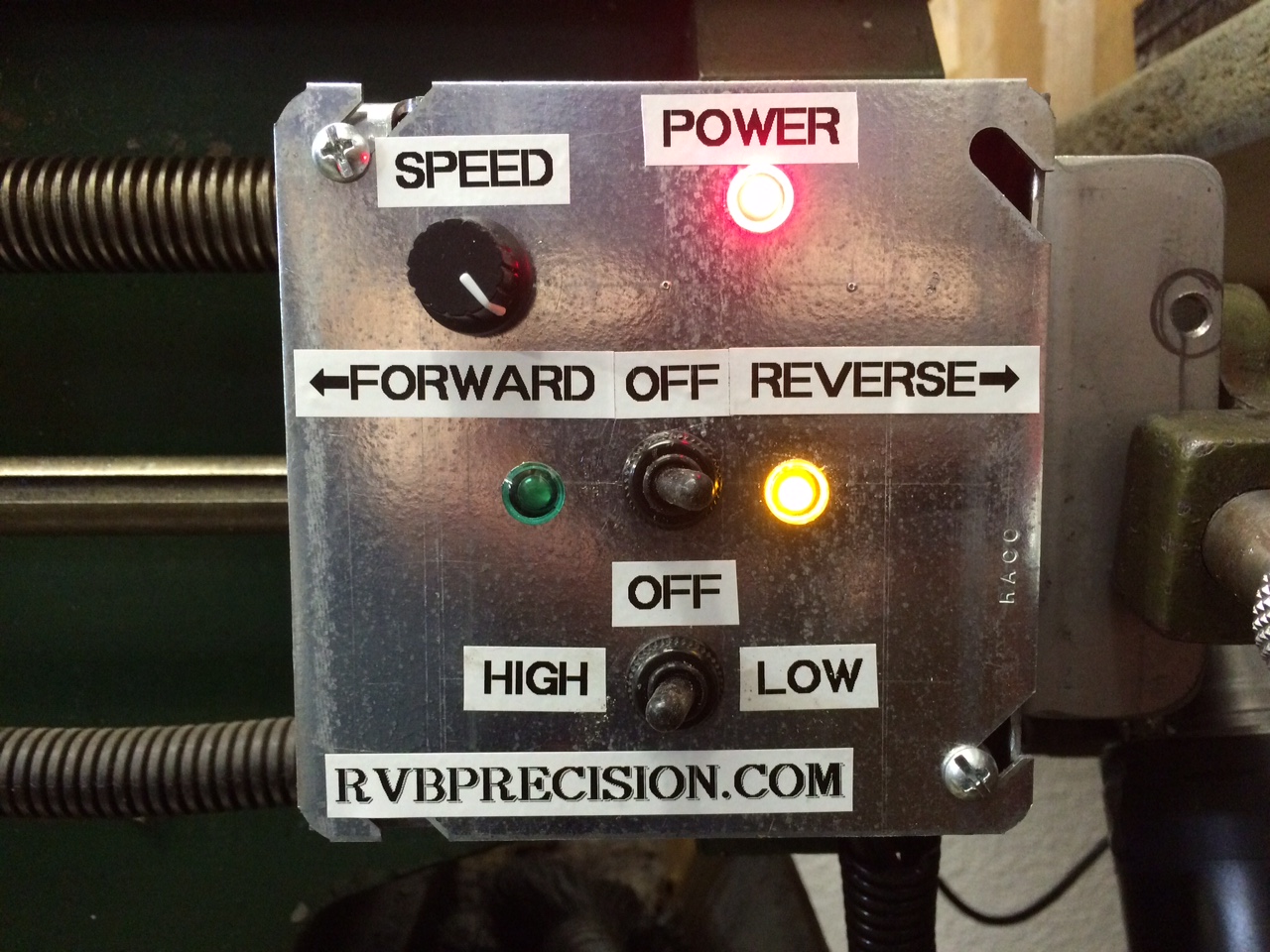
THERE, Now I think it’s finished!
Thanks!
5 comments on “Power Feed Modification on JET 12X36 Lathe”